


A fiberglass filter mesh can help remove slag, dross, oxides, and other non-metallic inclusions before molten metal enters the mold cavity. However, where the filter is placed in the gating system is just as important as the filter itself.
A filter that is installed in a highly turbulent area may clog quickly, become damaged, or provide poor filtration. A filter placed too far upstream may also allow new inclusions to enter the metal after filtration.
So, where should a fiberglass filter mesh be placed?
In most casting applications, the preferred location is in the runner or at a controlled filtration point between the sprue and the ingates. The exact position depends on the alloy, casting design, pouring conditions, and type of gating system.

This guide explains the most common positions and how to choose the right one.
The Basic Position of a Fiberglass Filter Mesh
A typical sand casting gating system can be simplified as:
Pouring Basin → Sprue → Sprue Well → Runner → Filter Mesh → Gate → Casting Cavity
The filter should be positioned so that all molten metal going to the casting cavity must pass through it.
For fiberglass mesh, two locations are particularly common:
- At the sprue base or near the sprue well
- Horizontally in the runner
SF-Foundry’s fiberglass mesh filter for aluminum casting is designed to be integrated into critical points of the gating system, with the sprue base and runner identified as practical placement locations.
However, these locations are not equally suitable for every application.
Best Position: In the Runner
For many applications, placing the fiberglass filter mesh in the runner is the most practical solution.
A typical arrangement is:
Sprue → Sprue Well → Runner → [Fiberglass Mesh] → Gate → Cavity
Why is the runner a good location?
By the time the molten metal reaches the runner:
- The high-energy vertical stream from the sprue has already changed direction.
- The sprue well can help absorb the initial impact.
- The metal flow can become more controlled.
- The filter can be properly supported.
- The filtered metal has a relatively short distance to travel before entering the cavity.
This makes the runner a good compromise between filtration effectiveness, installation stability, and gating-system design.
For ceramic filters, SF-Foundry’s existing installation guidance also identifies the horizontal runner as the most common and practical filtration position.
The same general principle can be applied when designing a fiberglass mesh filtration system.
Should the Filter Be Placed Directly Under the Sprue?
Usually, no.
Placing a flat fiberglass mesh directly underneath the sprue can expose it to the highest initial metal velocity and turbulence.
The simplified flow is:
Sprue ↓
High-velocity molten metal
Filter ← excessive impact
Runner → Casting
This can create several problems:
- The mesh may become damaged.
- Inclusions can accumulate rapidly in one area.
- The filter may clog prematurely.
- The filter may move or deform.
- Metal flow through the mesh may become uneven.
SF-Foundry’s fiberglass mesh troubleshooting guide identifies placing a filter in a turbulent zone, such as directly under the sprue, as one potential cause of rapid clogging.
A better design is:
Sprue → Sprue Well → Runner → Filter → Gate
The sprue well or directional change gives the metal a chance to lose some of its initial energy before filtration.
Filter Placement Near the Sprue Base
Although directly under a high-velocity sprue is generally undesirable, a controlled filtration position near the sprue base can be useful.
For example:
Sprue → Sprue Well → [Filter] → Runner
This arrangement can provide relatively early filtration while preventing contaminated metal from traveling through a long runner system.
It can be particularly useful when:
- The gating system is compact.
- There is limited runner length.
- Early filtration is desirable.
- The filter can be adequately supported.
- The mold design provides a dedicated filter pocket.
The important distinction is that the filter should not simply be dropped beneath the sprue. The gating system should be designed around the filter position.
The filter needs a stable seat and controlled flow path.
Placing the Filter Close to the Gates
Another possible position is:
Runner → [Filter] → Ingates → Casting
This places the filter relatively close to the cavity.
Advantages
The main advantage is that there is less opportunity for contamination to enter the metal after filtration.
This is important because filtration is not the final answer to every inclusion problem. If the runner downstream of the filter is poorly designed, turbulence, mold erosion, or reoxidation can introduce new inclusions after the metal has already passed through the filter.
Therefore, placing the filter relatively close to the ingates can provide an effective final filtration barrier.
Potential disadvantage
The filter may have to handle the entire flow immediately before the cavity.
This means the filter area, mesh opening, and gating dimensions must be appropriate for the required filling rate.
If the filter is too small or too fine, the result may be:
- Restricted metal flow
- Longer filling time
- Premature clogging
- Misruns or cold shuts
Therefore, “closer to the casting” does not automatically mean “better.”
The filter location must always be considered together with filter area and flow rate.
A Simple Comparison of Filter Locations
| Filter Position | Main Advantage | Main Risk | General Recommendation |
|---|---|---|---|
| Directly under sprue | Simple installation | High turbulence and impact | Usually avoid |
| Near sprue well | Early filtration | Requires good support and flow control | Good in suitable designs |
| In runner | Balanced filtration and flow | Requires correct filter seat | Preferred for many applications |
| Near ingates | Short post-filter flow path | Filter must handle final flow | Good for selected designs |
| Inside the cavity | Very late filtration | Difficult to control and support | Generally avoid |
This is a general design guide rather than a universal rule. Different alloys and casting processes may require different filter positions.

Why the Filter Should Not Be Too Far From the Casting
One important principle is:
The cleaner the metal needs to remain after filtration, the shorter the downstream flow path should generally be.
Imagine two designs.
Design A
Sprue → Filter → Long Runner → Several Bends → Gates → Casting
Design B
Sprue → Runner → Filter → Short Runner → Gates → Casting
Design B generally provides better control over the metal after filtration because there is less runner length available for:
- Mold erosion
- Oxide formation
- Reoxidation
- Re-entrainment of inclusions
This principle is also reflected in SF-Foundry’s broader filtration guidance, which recommends positioning filters relatively close to the casting cavity when minimizing post-filtration contamination is important.
However, this does not mean moving every filter immediately next to the gate. The filter still needs sufficient area, support, and stable metal flow.
Horizontal or Vertical Placement?
The filter’s orientation is another important consideration.
Horizontal Placement
For many sand casting gating systems, a flat fiberglass mesh can be placed horizontally in the runner.
Advantages:
- Simple mold design
- Easy installation
- Large filtration area
- Easy inspection
- Suitable for many gravity casting applications
A typical configuration is:
Runner → [Horizontal Mesh Filter] → Gate
This is generally the easiest arrangement for flat fiberglass mesh.
Vertical Placement
A vertical filter can also be used in certain gating designs.
For example:
Runner → | Filter | → Runner
This configuration can be useful when:
- Mold space is limited.
- The gating system is vertically oriented.
- The filter is supported by a dedicated pocket.
- The casting requires a different flow arrangement.
However, vertical installation requires careful attention to filter support and sealing.
The filter must remain stable during pouring and must not allow molten metal to bypass the filtration surface.
The Filter Seat Is Just as Important as the Filter Position
Even if the filter is installed in the correct location, it may not work properly if the filter seat is poorly designed.
The basic requirements are:
1. Full support
The mesh should be adequately supported so that molten metal pressure does not deform or tear it.
2. Correct dimensions
The filter should fit the designed filtration area without leaving a large gap around its edges.
3. Good sealing
Molten metal must not be able to flow around the filter.
If metal bypasses the mesh, the filter may appear to be installed correctly while providing little actual filtration.
4. Smooth transition
The gating system should guide metal toward the filter rather than creating a concentrated jet against one small section.
This is particularly important for lightweight fiberglass mesh.
Filter Placement Depends on the Casting Process
There is no single filter position that works for every metal casting application.
Aluminum Casting
Fiberglass mesh filters are commonly used for aluminum filtration because they provide a relatively simple physical barrier for non-metallic inclusions.
For aluminum sand or gravity casting, a practical arrangement is often:
Pouring Basin → Sprue → Runner → Fiberglass Mesh → Gate → Cavity
SF-Foundry’s aluminum fiberglass mesh filter is specifically designed for integration into sprues, runners, or gates, with the sprue base and runner listed as common placement points.
Iron Casting
Iron requires more careful consideration because of its higher pouring temperature and the mechanical and thermal demands placed on the filter.
The filter must be suitable for the temperature and properly supported.
For more demanding iron applications, ceramic foam filters may be preferred when deeper filtration and higher filtration performance are required.
SF-Foundry’s existing iron filtration guidance distinguishes fiberglass/RGF filters from ceramic foam filters and emphasizes correct filter area, seating, and placement.
Therefore, do not select fiberglass mesh simply because it is inexpensive. Select it according to the alloy, temperature, casting weight, inclusion load, and required filtration level.
How to Choose the Best Position: A Practical Checklist
Before deciding where to install the fiberglass mesh, ask these questions:
Question 1: Where is the metal flow most stable?
Avoid placing the mesh directly in a high-energy metal jet.
Question 2: Can all metal be forced through the filter?
If metal can flow around the filter, its filtration function is compromised.
Question 3: Is there enough filter area?
A small mesh filter may restrict flow or clog quickly.
Question 4: How much runner exists after the filter?
If there is a long, turbulent runner after filtration, new inclusions may enter the metal.
Question 5: Can the filter be securely supported?
The filter should not float, shift, bend, or tear during pouring.
Question 6: Is the filter compatible with the alloy and temperature?
Fiberglass mesh specifications vary. Select the appropriate material and construction for the actual casting process.
A Practical Rule for Foundry Engineers
If you need a simple starting point, use this principle:
Place the fiberglass filter mesh in a stable section of the runner, after the metal has passed through the high-energy sprue region but before the gates, with enough filter area and support to allow the required metal flow.
In many cases, the basic arrangement can be:
Pouring Basin → Sprue → Sprue Well → Runner → [Fiberglass Filter Mesh] → Gate → Casting
Then optimize the exact position according to:
- Alloy
- Casting weight
- Pouring temperature
- Pouring rate
- Runner design
- Filter mesh size
- Filter area
- Inclusion level
- Required casting quality
This approach is much more reliable than choosing the filter position based only on convenience.
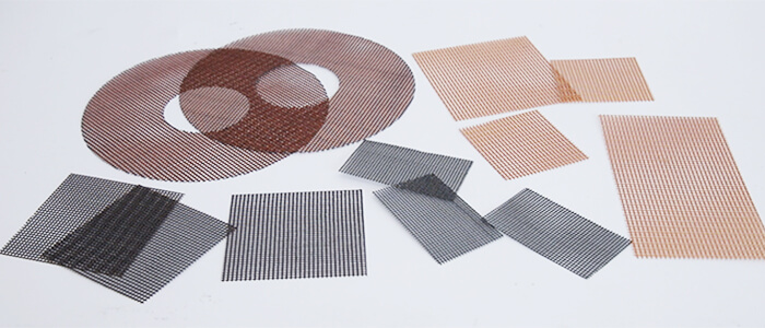
Fiberglass Mesh Filter Placement vs. Ceramic Foam Filter Placement
Fiberglass mesh and ceramic foam filters should not always be treated as interchangeable.
| Factor | Fiberglass Mesh | Ceramic Foam Filter |
|---|---|---|
| Structure | 2D woven mesh | 3D porous structure |
| Main mechanism | Screening | Screening + depth filtration |
| Installation | Relatively simple | Requires dedicated filter seat |
| Typical use | Cost-effective filtration | Higher-performance filtration |
| Flow resistance | Generally lower | Generally higher |
| Custom cutting | Easy for sheet mesh | Usually fixed dimensions |
| Best application | High-volume / suitable non-ferrous applications | More demanding filtration applications |
SF-Foundry’s existing comparison article also positions glass fiber mesh as a practical option for cost-sensitive, high-volume casting applications, while ceramic foam filters are more appropriate when higher filtration performance is required.
The correct question is therefore not simply:
“Where should I put the filter?”
It is:
“What filter should I use, where should I put it, and can the gating system support the required flow?”
Common Placement Mistakes
Mistake 1: Putting the mesh directly under the sprue
This exposes the filter to excessive turbulence and concentrated flow.
Mistake 2: Making the filter too small
A small filter can restrict filling and clog quickly.
Mistake 3: Leaving gaps around the filter
Molten metal may bypass the filtration surface.
Mistake 4: Installing the filter too early
If there is a long runner after filtration, the metal can become contaminated again.
Mistake 5: Installing the filter too close to a gate without considering flow
The filter may become the primary flow restriction.
Mistake 6: Choosing mesh size without considering casting conditions
A finer mesh is not automatically better. Filtration performance must be balanced with flow capacity and clogging resistance.
How Fiberglass Filter Mesh Fits Into a Complete Gating System
A filter should not be considered an isolated consumable.
A properly designed casting system may combine:
Pouring Cup → Sprue → Sprue Well → Runner → Filter → Gate → Casting
Each component has a different function:
| Component | Main Function |
|---|---|
| Pouring cup | Receive and control incoming molten metal |
| Sprue | Transport metal downward |
| Sprue well | Reduce impact and change flow direction |
| Runner | Distribute metal |
| Fiberglass mesh | Remove larger non-metallic inclusions |
| Gate | Control metal entry into the cavity |
| Casting cavity | Form the final component |
SF-Foundry’s broader gating and filtration guidance emphasizes that filtration works best as part of an integrated gating system rather than as an isolated component.
Final Takeaway
Where should a fiberglass filter mesh be placed in a gating system?
For many applications, the best starting point is:
In the runner, after the sprue well and before the gates.
This position provides a good balance between:
- Controlled metal flow
- Inclusion removal
- Filter protection
- Easy installation
- Short downstream flow distance
However, the exact position should be adjusted according to the alloy, casting size, pouring rate, gating geometry, filter area, and required filtration performance.
Most importantly, do not treat filter placement as an afterthought. The filter, filter seat, runner dimensions, and metal flow should be designed as one system.
If you are unsure whether a fiberglass mesh should be installed at the sprue base, in the runner, or near the ingates, review the complete gating layout before selecting the filter.
Frequently Asked Questions
Can fiberglass filter mesh be placed directly under the sprue?
It can be done in some designs, but it is generally not the preferred position for a flat mesh because the high-velocity metal stream can cause excessive impact and premature clogging.
Is it better to place the filter near the sprue or near the gate?
Neither is universally better. A runner position between the sprue well and gates is often a good compromise. The best location depends on flow conditions and the purpose of filtration.
Can fiberglass mesh be installed horizontally?
Yes. Horizontal placement in a runner is one of the most practical configurations for flat fiberglass mesh.
Can one filter be used for multiple gates?
Yes, if the gating system distributes the metal evenly and the filter has sufficient area and flow capacity. For larger or more complex castings, multiple filters may be more appropriate.
Is fiberglass mesh suitable for all metals?
No. Filter material and construction should be selected according to alloy, pouring temperature, casting size, flow rate, and required filtration performance.
How do I choose the right fiberglass mesh filter?
Start with the alloy and casting conditions, then consider mesh opening, filter area, gating position, pouring rate, and expected inclusion load. The filter should provide sufficient filtration without excessively restricting the metal flow.
Need Help Selecting the Right Fiberglass Filter Mesh?
The correct mesh size is only one part of the equation. Filter position, filter area, gating design, and metal flow all affect the final result.
SF-Foundry supplies fiberglass mesh filters for metal casting and can help match the filter specification to your casting application.
If you know your alloy, casting weight, pouring temperature, gating layout, and required mesh size, these details can be used to determine a more suitable filter configuration for your process.