


A well-designed runner system is essential for controlling how molten metal flows into a sand mold.
In sand casting, the runner is part of the gating system that distributes molten metal from the sprue to the ingates and ultimately into the mold cavity. Its design can significantly affect filling behavior, turbulence, slag entrainment, temperature loss, and casting quality.
However, there is no single runner design suitable for every casting.
The correct runner system depends on factors such as the alloy, casting size, geometry, pouring temperature, mold type, and required filling time.
This guide explains the basic principles of runner system design for sand casting and the key factors engineers should consider.
What Is a Runner System in Sand Casting?
A runner system is the horizontal flow channel that carries molten metal from the sprue to one or more ingates.
A typical sand casting gating system includes:
- Pouring basin or pouring cup
- Sprue
- Sprue well
- Runner
- Runner extension
- Ingate
- Mold cavity

The runner acts as a distribution channel between the vertical sprue and the casting cavity.
A properly designed runner should help deliver molten metal to the mold cavity at an appropriate flow rate while minimizing turbulence, air entrainment, slag entry, and excessive heat loss.
What Is the Main Purpose of a Runner?
The runner does more than simply transport molten metal.
A well-designed runner system can help:
- Distribute molten metal to multiple ingates
- Control metal flow
- Reduce excessive turbulence
- Promote smoother mold filling
- Help separate slag and inclusions
- Reduce erosion of the sand mold
- Control filling time
- Improve consistency between castings
For complex castings, runner design becomes especially important because molten metal may need to be distributed to multiple areas of the mold at nearly the same time.
Step 1: Understand the Casting Requirements
Runner design should begin with the casting itself.
Before determining runner dimensions, engineers should evaluate:
- Casting weight
- Casting geometry
- Section thickness
- Alloy type
- Pouring temperature
- Required pouring time
- Number of cavities
- Mold material
- Casting orientation
For example, a thin-wall iron casting and a heavy steel casting require very different gating strategies.
The goal is not simply to design a larger runner.
The goal is to create a gating system that delivers molten metal into the mold cavity under controlled conditions.
Step 2: Determine the Required Filling Time
Filling time is one of the fundamental considerations in gating system design.
If the mold fills too slowly, the molten metal may lose excessive heat before the cavity is completely filled.
This can increase the risk of:
- Misruns
- Cold shuts
- Incomplete filling
If the mold fills too quickly, excessive flow velocity may cause:
- Turbulence
- Sand erosion
- Mold damage
- Oxide formation
- Gas entrapment
The appropriate filling time depends on the alloy and casting design.
Factors influencing filling time include:
- Metal fluidity
- Pouring temperature
- Casting wall thickness
- Casting weight
- Mold material
- Complexity of the casting
Once the required pouring time is estimated, the gating system area can be calculated to achieve the desired flow rate.
Step 3: Select the Gating System Type
Runner design is closely related to the overall gating system.
Two common approaches are:
Pressurized Gating System
In a pressurized gating system, the total cross-sectional area generally decreases along the direction of metal flow.
The choke area restricts the flow and helps maintain pressure within the gating system.
Typical characteristics include:
- Higher flow velocity
- Compact gating design
- Faster mold filling
- Greater sensitivity to turbulence
Pressurized systems may be suitable when rapid filling is required, but careful design is necessary to avoid excessive turbulence.
Unpressurized Gating System
In an unpressurized gating system, the total cross-sectional area generally increases along the flow path.
This helps reduce flow velocity as molten metal moves through the gating system.
Typical characteristics include:
- Lower metal velocity
- Smoother filling
- Reduced turbulence
- Larger gating channels
Unpressurized systems are often preferred when smoother metal flow is important.
The correct system depends on the alloy and casting requirements.
Step 4: Determine the Gating Ratio
The gating ratio describes the relationship between the cross-sectional areas of different parts of the gating system.
It is commonly expressed as:
Sprue Area : Runner Area : Total Ingate Area
For example:
1 : 2 : 2
or
1 : 4 : 4
The exact gating ratio varies according to the casting alloy and gating philosophy.
A gating ratio should not be copied blindly from another casting.
Engineers should consider:
- Metal type
- Oxidation tendency
- Desired flow velocity
- Casting geometry
- Mold filling behavior
In general, the gating ratio helps engineers control how the available flow area changes throughout the system.
Step 5: Design the Runner Cross Section
The cross-sectional shape of the runner affects metal flow and heat transfer.
Common runner cross sections include:
- Rectangular
- Trapezoidal
- Circular
- Semi-circular
Trapezoidal Runner
Trapezoidal runners are commonly used in sand casting because they are relatively easy to form and can provide favorable flow characteristics.
They are also practical when molding patterns are used to create the gating system.
Rectangular Runner
Rectangular runners are simple to produce but sharp corners may influence flow behavior and heat transfer.
Circular Runner
Circular runners can provide a favorable surface-area-to-volume relationship, but they may be more difficult to produce in conventional sand molds.
The selection should consider both casting performance and manufacturing practicality.
Step 6: Determine Runner Size
Runner size should be calculated based on the required metal flow rate and gating system design.
An undersized runner may create excessive resistance and reduce the metal supply to the ingates.
An oversized runner may:
- Increase metal consumption
- Increase heat loss
- Reduce yield
- Take longer to solidify
- Add unnecessary machining or recycling costs
The runner should therefore be large enough to supply molten metal efficiently but not unnecessarily oversized.
Runner dimensions are normally determined together with:
- Sprue dimensions
- Choke area
- Ingate area
- Required pouring time
- Metal flow rate
For production castings, simulation software or previous casting data can be valuable for optimizing these dimensions.
Step 7: Use Smooth Flow Transitions
Sudden changes in direction or cross-sectional area can create turbulence.
When designing a runner system, smooth transitions are generally preferred.
Consider:
- Avoiding sharp corners where possible
- Using gradual changes in cross-sectional area
- Designing smooth runner-to-ingate connections
- Avoiding unnecessary flow restrictions
The goal is to guide molten metal into the mold cavity with as little uncontrolled turbulence as possible.
Step 8: Add a Sprue Well
A sprue well is commonly placed at the bottom of the sprue.
Its purpose is to reduce the direct impact of high-velocity molten metal entering the runner.
Without a suitable transition, metal falling through the sprue can strike the runner and create turbulence.
A properly designed sprue well can help:
- Reduce turbulence
- Change flow direction
- Protect the runner entrance
- Promote smoother metal flow
The runner should ideally receive molten metal after its velocity has been controlled rather than directly from the falling metal stream.
Step 9: Consider a Runner Extension
A runner extension is a continuation of the runner beyond the last ingate.
It can help trap the first metal entering the gating system, which may contain:
- Oxides
- Slag
- Sand particles
- Other contaminants
Instead of allowing this material to immediately enter the casting cavity, the runner extension provides an area where unwanted material can continue moving beyond the ingates.
Runner extensions can be particularly useful when clean molten metal flow is important.
Step 10: Position the Ingates Correctly
The relationship between the runner and ingates is critical.
The ingate should deliver molten metal into the casting cavity in a controlled manner.
When positioning ingates, consider:
- Casting geometry
- Wall thickness
- Filling direction
- Temperature loss
- Solidification behavior
- Turbulence risk
For multiple ingates, the runner should distribute metal as evenly as possible.
Poor ingate positioning can result in:
- Uneven filling
- Cold shuts
- Air entrapment
- Localized turbulence
- Temperature differences
Runner design should therefore always be evaluated together with ingate design.
Common Runner System Design Mistakes
Several common mistakes can negatively affect casting quality.
1. Making the Runner Too Small
An undersized runner may restrict molten metal flow and prevent the cavity from filling properly.
Possible consequences include:
- Misruns
- Cold shuts
- Incomplete filling
2. Making the Runner Too Large
An oversized runner increases unnecessary metal consumption and reduces casting yield.
It may also increase heat loss and complicate cleaning operations.
3. Ignoring Turbulence
Fast or uncontrolled metal flow can cause:
- Oxide inclusions
- Gas entrapment
- Mold erosion
- Slag entrainment
Runner design should focus on controlled flow rather than maximum flow velocity.
4. Using Sharp Direction Changes
Sharp turns can disturb the molten metal flow.
Whenever possible, smoother transitions should be considered.
5. Ignoring the Runner Extension
Without a runner extension, the first metal entering the gating system may flow directly toward the casting cavity.
A properly designed extension can help reduce the risk of contaminants entering the casting.
6. Designing the Runner Independently
A runner should never be designed as an isolated component.
It must work together with:
- Pouring cup
- Sprue
- Sprue well
- Ingate
- Riser system
- Casting geometry
A good runner design is part of an optimized overall gating system.
How Does the Metal Type Affect Runner Design?
Different alloys have different flow characteristics.
Cast Iron
Cast iron generally has good fluidity, but gating design should still control turbulence and slag entry.
Runner systems for iron castings often focus on stable metal distribution and clean filling.
Steel
Steel has a higher pouring temperature and can lose heat rapidly.
Runner design must consider:
- Temperature loss
- Filling time
- Mold erosion
- Oxidation
Can Casting Simulation Improve Runner Design?
Yes.
Modern casting simulation software can help engineers evaluate:
- Filling time
- Metal velocity
- Turbulence
- Temperature distribution
- Air entrapment
- Solidification behavior
Simulation does not completely replace foundry experience, but it can significantly reduce trial-and-error during gating system development.
For new or complex castings, simulation can help identify potential problems before physical production begins.
Runner System Design Checklist
Before finalizing a runner design, consider the following questions:
Casting
- What alloy is being poured?
- What is the casting weight?
- What are the minimum wall thicknesses?
Pouring
- What is the pouring temperature?
- What is the target filling time?
- What flow rate is required?
Gating System
- Is the system pressurized or unpressurized?
- What is the gating ratio?
- Where is the choke located?
Runner
- Is the cross-sectional area sufficient?
- Is the runner shape suitable?
- Are transitions smooth?
- Is a runner extension required?
Casting Quality
- Is turbulence controlled?
- Can slag enter the casting cavity?
- Is mold erosion likely?
- Are multiple cavities filled consistently?
Conclusion
Designing a runner system for sand casting requires more than selecting a channel size.
The runner must work as part of the complete gating system to control molten metal flow from the sprue to the casting cavity.
Key considerations include:
- Casting requirements
- Alloy type
- Filling time
- Gating ratio
- Runner cross-sectional area
- Runner shape
- Flow transitions
- Sprue well design
- Runner extension
- Ingate position
There is no universal runner design suitable for every casting.
The most effective design is one that balances filling speed, flow stability, casting quality, and metal yield according to the specific casting process.
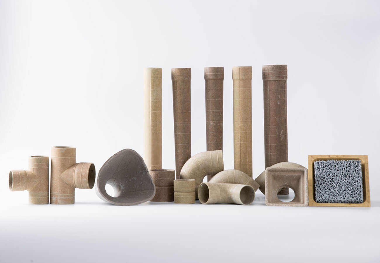
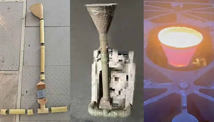
For foundries using preformed runner systems or casting gating components, standardized runner products can also help improve dimensional consistency and simplify mold preparation.
SF-Foundry supplies casting solutions and foundry consumables for metal casting processes. Contact us to discuss your gating system and foundry application requirements.
Email: info@sf-foundry.com
WhatsApp: +8618636913699