


You’ve dialed in your alloy chemistry. Your furnace temperature is spot on. Yet castings still come out with slag inclusions, sand holes, or porosity. The problem often isn’t the metal—it’s what happens after the pour starts.
Installing a honeycomb ceramic filter in your sand casting gating system is one of the most effective ways to trap inclusions, reduce turbulence, and improve casting quality. But simply dropping a filter into the mold isn’t enough. Proper installation—from selection to preheating to sealing—is what separates clean, consistent castings from expensive rework.
This guide walks you through every practical step of installing honeycomb ceramic straight-hole filters in sand casting molds.
Before You Start: Select the Right Filter
Installation begins at the selection stage. Three variables determine whether your filter protects your casting or fails it: material, pore density, and physical dimensions.
Understand What a Honeycomb Ceramic Filter Is
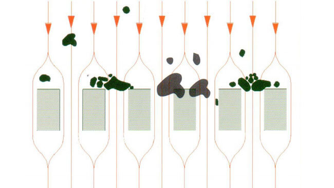
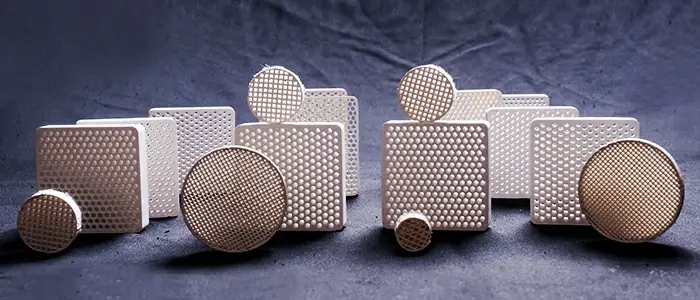
A honeycomb ceramic filter is a high-strength filter made of mullite or cordierite ceramic material with a straight-pore honeycomb structure. Unlike foam ceramic filters (which have a three-dimensional network of random pores), honeycomb filters feature hundreds of parallel, straight channels running through the ceramic block. Metal flows straight through these channels, and inclusions larger than the pore size are trapped at the channel entrances.
Think of it as: a gate with bars—big things can’t pass, but everything else flows through.
Honeycomb ceramic filters are used across a wide range of metals—gray iron, ductile iron, malleable iron, and more.
Select Pore Density
Honeycomb ceramic filters are typically specified by pore density measured in PCSI (Pores Per Square Inch) . Common densities include 100 PCSI, 200 PCSI, and 300 PCSI. The higher the pore density, the finer the filtration—but the greater the flow restriction.
| Pore Density | Best For | Flow Rate |
|---|---|---|
| 100 PCSI | Large castings, high flow rate requirements | Highest |
| 200 PCSI | General-purpose iron and aluminum casting | Moderate |
| 300 PCSI | Smaller castings requiring finer filtration | Lower |
Size the Filter Correctly
The filter’s cross-sectional area should be sufficient to handle the metal flow without becoming a choke point. Common honeycomb filter dimensions range from 37×37 mm up to 81×81 mm for square shapes, and Φ30 to Φ90 mm for round ones, with thickness between 12 and 22 mm.
Regular sizes and their filtration capacity for different metals:
| Size (mm) | Pore Density (PCSI) | Max Filtration Weight—Gray Iron (kg) | Max Filtration Weight—Ductile Iron (kg) | Max Filtration Weight—Aluminum (kg) |
|---|---|---|---|---|
| 37×37 | 100, 300 | 35 | 25 | 15 |
| 40×40 | 100, 300 | 40 | 30 | 20 |
| 43×43 | 100, 300 | 55 | 50 | 30 |
| 50×50 | 100, 200 | 70 | 58 | 40 |
Step 1: Inspect the Filter Before Installation
Never install a damaged filter.
Before you begin, inspect every filter surface. Look for cracks, chips, or corner damage. Run your gloved hand across all faces—surface breaks feel like rough edges or dents. Use strong light to see through the filter and check for internal cracks.
Why this matters: A filter with pre-existing damage becomes a failure point under thermal and mechanical load during pouring. Even worse, filter fragments can break off and enter the casting, creating new defects instead of solving them.
Step 2: Design the Filter Cavity (Seat) in the Mold
Before you can install the filter, you need a properly designed cavity in the sand mold to receive it.
Cavity Design Guidelines
-
Gap allowance: The recommended gap around the filter is no more than 1–2 mm per side.
-
Sealing: Use refractory mud or ceramic fiber gasket material to seal the gap (gap ≤1mm).
-
Support surface flatness: The support surface flatness error should be ≤ 0.5 mm.
-
Support structure: A stepped filter seat design helps reduce bottom stress.
Positioning the Filter in the Gating System
Where you place the filter is just as important as how you place it.
The Golden Rule: Place the filter as close to the casting cavity as possible, typically in the runner. This traps inclusions before they can enter the casting.
Recommended installation positions:
| Position | Best For | Key Advantage |
|---|---|---|
| Cross runner (horizontal) | Most sand casting applications | Most recommended; converts turbulent flow to laminar flow |
| Pouring cup area | Manual wet sand molding, DISA lines | Primary filtration; easy to observe and replace |
| Bottom of sprue | Complex systems, multi-cavity molds | Balances flow across multiple cavities |
Avoid: Placing the filter in the downsprue, which can create destructive jetting. Horizontal installation at the sprue bottom is also not recommended—vertical installation in the runner is preferred to reduce turbulence interference.
The closer the placement position is to the casting cavity, the better. For the cross runner position, installing the filter vertically allows the thicker filter sheet to withstand continuous scouring of the molten metal. The recommended distance from the pouring cup is 50–100 mm.
Step 3: Prepare the Filter Seat
Once the mold is rammed and the filter cavity is formed:
-
Clean the cavity: Use high-pressure gas to remove loose sand and debris from the filter seat.
-
Check the fit: Place the filter into the cavity without sealing material first. It should sit level and fit snugly—not too tight (risk of chipping) and not too loose (risk of bypass flow).
-
Apply refractory sealant: Always apply a high-temperature ceramic fiber gasket paper or refractory paste around the filter’s edges before final seating. This creates a positive seal and prevents metal bypass.
Why sealing matters: If molten metal flows around—not through—the filter, filtration is completely ineffective. Turbulent flow through gaps can also erode the filter cavity refractory material, introducing new inclusions into the metal.
Step 4: Preheat the Filter
This is the most critical step—and the most commonly skipped.
Placing a cold or only partially warmed filter into the gating system before pouring causes severe thermal shock. The dramatic temperature difference between the filter (room temperature) and the molten metal causes thermal stress that can crack or shatter the ceramic structure.
Preheating Protocol
| Parameter | Recommendation |
|---|---|
| Preheat temperature | 600–800°C (adjusted according to filter size) |
| Preheat time | ≥30 minutes (large filters need to be extended to 1 hour) |
| Heating rate | ≤10°C/minute to avoid thermal stress cracks |
| Target | Match the filter temperature as close as possible to the metal pouring temperature |
Critical: Never use an open torch for direct preheating, as it creates severe hotspots that lead to uneven expansion and cracking. Always use a dedicated preheating furnace.
Handling After Preheating
Complete installation within 10 minutes after preheating. The longer the filter sits outside the preheating furnace, the more it cools, increasing thermal shock risk at pour time. Use insulated tongs or gloves to handle the hot filter.
Step 5: Install the Filter in the Mold
With the filter preheated and the mold ready:
-
Lower the filter straight down into the prepared seat. Use a tool or guide to ensure it goes in level.
-
Ensure it sits perfectly horizontal (for runner installation) and is fully seated against the sealing material.
-
Close the mold carefully, ensuring the filter remains in position and isn’t dislodged.
Avoid: Tilting the filter or placing it on an uneven surface. A tilted or unevenly seated filter causes preferential metal flow through one section, leading to premature clogging and reduced effective filtration area.
Step 6: Pour with Control
Even with perfect installation, pouring technique matters:
-
Start slow: Maintain 50% of normal flow rate for the first 2–3 seconds of pouring. This allows the metal to gently prime the filter before full flow begins.
-
Control impact height: Keep the free-fall height of molten metal under control to avoid excessive impact force on the filter.
-
Pouring speed guidelines:
| Metal Type | Recommended Pouring Speed | Maximum Impact Height |
|---|---|---|
| Aluminum alloy | 0.5–1.2 kg/s | ≤150 mm |
| Cast iron | 1.5–3.0 kg/s | ≤100 mm |
| Copper alloy | 0.8–1.8 kg/s | ≤120 mm |
Monitor during pour: The pouring cup installation allows you to observe the impact resistance of the filter in real time, making it convenient to handle abnormal situations quickly.
Common Installation Mistakes to Avoid
Based on foundry industry experience, here are the most frequent installation failures:
| Mistake | Consequence | Prevention |
|---|---|---|
| Inadequate or uneven preheating | Instant cracking or shattering; reduced flow rate; gas evolution | Preheat to 600–800°C for ≥30 min in a dedicated furnace |
| Incorrect fit / lack of sealing | Bypass flow (metal goes around, not through); erosion of filter box | Use refractory sealant; maintain ≤1–2 mm gap per side |
| Rough handling | Chips, cracks, crushed edges that become failure points | Handle gently with gloves; store on flat padded surfaces |
| Tilted or uneven placement | Uneven flow distribution; premature clogging | Lower filter straight down; ensure level seating |
| Filter not locked in position | Filter shifts or falls out during mold handling | Ensure tight fit with proper sealing; check before closing mold |
Post-Installation Checklist
Before you pour, run through this quick checklist:
-
Filter inspected for cracks or damage
-
Filter cavity correctly sized (≤1–2 mm gap per side)
-
Refractory sealant applied around edges
-
Filter preheated to 600–800°C for ≥30 minutes
-
Filter installed within 10 minutes of preheating
-
Filter sits level and fully seated
-
Mold closed without dislodging the filter
-
Pouring plan includes slow start (50% flow for 2–3 seconds)
Summary
Installing honeycomb ceramic filters in sand casting molds requires precision and discipline. The difference between a filter that works and one that fails often comes down to three things:
-
Preheat properly — 600–800°C for at least 30 minutes. No shortcuts.
-
Seal completely — No gaps means no bypass flow.
-
Place strategically — In the runner, as close to the casting as possible.
When properly applied, honeycomb ceramic filters—with their straight-pore structure and high strength—can effectively remove inclusions, reduce turbulent flow, and stabilize mold filling. The result is cleaner castings with fewer defects and more consistent quality.