

You’ve just poured a batch of ductile iron castings. After shakeout and machining, you see it: dark, irregular cavities—especially in the thickest sections. Your first thought is inclusions, but the cavities have a rough, crystalline surface. That’s shrinkage porosity.
Shrinkage is one of the most frustrating defects in ductile iron casting. It doesn’t come from dirty metal or poor filtration. It comes from one simple fact: liquid metal takes up less space when it solidifies. If you don’t provide extra liquid metal to compensate, the last part to freeze pulls metal from wherever it can – leaving voids.

The good news is that shrinkage is highly predictable and preventable. The right riser (feeder) system is your most powerful tool.
What Shrinkage Looks Like in Ductile Iron
| Feature | Description |
|---|---|
| Location | Thick sections, thermal centres, under risers (if riser froze early), opposite gates |
| Appearance on machined surface | Dark, spongy, or irregular cavities |
| Fracture surface | Rough, crystalline – not smooth or flaky |
| X‑ray | Dark areas (less dense), often branched or clustered |
| Pressure test | Leaks (if connected to surface) |
Unlike inclusion defects (which are smooth, dark, or layered), shrinkage has a metallic, jagged look because it’s a void, not a trapped particle.
Why Ductile Iron Shrinks – The Science
All metals contract when they solidify. Ductile iron is no exception. But ductile iron has a special behaviour that makes feeding different from gray iron and steel.
The Three Stages of Contraction
| Stage | What Happens | Volume Change |
|---|---|---|
| 1. Liquid contraction | Metal cools from pouring temperature to liquidus | Minor shrinkage |
| 2. Solidification contraction | Primary austenite forms | Significant shrinkage |
| 3. Solid contraction | Solid metal cools to room temperature | Small shrinkage (compensated by mould) |
The Graphite Expansion Effect
In gray iron, graphite precipitates as flakes during solidification and causes expansion that can self‑feed the casting. In ductile iron, graphite precipitates as spheroids, which occurs later – most of the expansion happens after the main feeding period.
Result: Ductile iron is more prone to shrinkage than gray iron because the beneficial expansion comes too late to help. You cannot rely on graphite expansion to eliminate risers. You must provide adequate external feeding.
Shrinkage Types in Ductile Iron
| Type | Cause | Appearance |
|---|---|---|
| Macro‑shrinkage (pipe) | Large cavity, insufficient feed metal | Single large void, often under riser |
| Micro‑shrinkage (porosity) | Poor interdendritic feeding | Fine, dispersed voids – “spongy” |
| Centreline shrinkage | Thermal gradient imbalance | Linear voids along centre of section |
Common Causes of Shrinkage in Ductile Iron
| Cause | Why It Happens |
|---|---|
| Riser too small | Not enough metal to feed the solidifying casting |
| Riser solidifies too early | Feeding stops before casting is solid |
| No exothermic/insulating sleeve | Sand riser chills the metal, losing feed ability quickly |
| Riser neck too small or too long | Metal freezes in the neck, cutting off feed |
| Pouring temperature too low | Metal starts freezing earlier, requires larger riser |
| Heavy section with poor directional solidification | Hot spot isolated from riser |
| Incorrect modulus ratio | Riser modulus less than casting modulus at the hot spot |
The single most common cause in ductile iron is premature solidification of the riser. Because ductile iron is poured slightly cooler than gray iron (≈1380‑1450°C vs. 1350‑1400°C), risers freeze quickly if not insulated or heated.
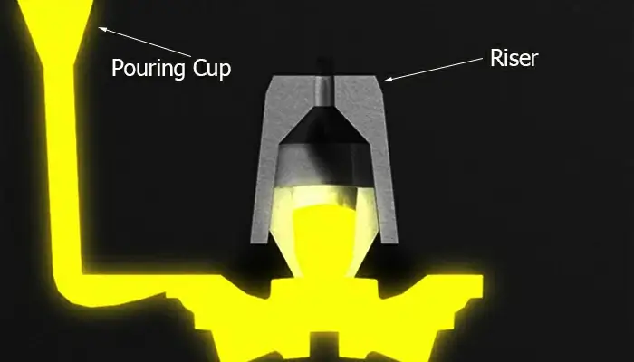
How the Right Riser Solves Shrinkage
A riser works by staying liquid long enough to feed the casting. There are three ways to extend riser solidification time:
| Method | Mechanism | Effectiveness |
|---|---|---|
| Larger sand riser | More volume = more heat | Poor, wasteful |
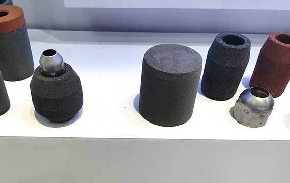
| Insulating sleeve | Slows heat loss | Good, cost‑effective |
| Exothermic sleeve | Generates additional heat | Best for heavy sections, high yield |
The Modulus Principle
The ability of a riser to feed depends on its modulus (volume ÷ cooling surface area). A higher modulus means slower cooling.
Rule: Riser modulus must be greater than the modulus of the casting section it feeds. For ductile iron, aim for:
-
Sand riser: M_riser ≥ 1.2 × M_casting (impractical, large)
-
Insulating sleeve: M_riser ≥ 1.0 × M_casting (often sufficient)
-
Exothermic sleeve: M_riser ≥ 0.8 × M_casting (smaller riser, higher yield)
Exothermic vs. Insulating for Ductile Iron
| Sleeve Type | Best for Ductile Iron? | Why |
|---|---|---|
| Insulating | Yes – for small to medium castings | Low cost, extends feed time by slowing cooling |
| Exothermic | Yes – for large, heavy sections, or high‑yield needs | Actively generates heat, extends feed time even longer |
| Hybrid (exothermic + insulating) | Ideal for large ductile iron castings | Best of both worlds: heat generation + insulation |
Recommendation: For most ductile iron castings, an exothermic or hybrid riser sleeve gives the best balance of yield and reliability. The extra cost pays for itself in fewer shrinkage defects and lower cleaning labour.
How to Choose the Right Riser – Step by Step
Step 1 – Identify the Hot Spot
The hot spot is the last area to solidify. It’s usually the thickest section or where sections join. Use a thermal simulation or simply examine the casting geometry.
Step 2 – Calculate the Modulus
For a simple plate or bar:
-
Modulus = Volume / Cooling surface area (in cm or inches)
For a cylinder (typical riser shape):
-
Modulus = D ÷ 4 (for D = diameter, height ≥ D)
Step 3 – Determine Required Riser Modulus
-
For sand riser: M_riser = 1.2 × M_hotspot
-
For insulating sleeve: M_riser = 1.0 × M_hotspot
-
For exothermic sleeve: M_riser = 0.8 × M_hotspot
Step 4 – Select Sleeve Size
Based on the required modulus, read from sleeve supplier tables. For example, if M_riser = 2 cm, an exothermic sleeve with D = 8 cm (M = D/4 = 2 cm) would work.
Step 5 – Check Riser Neck Design
The neck should be short and wide enough to stay open until the casting is fed. For ductile iron, a breaker core (reduced section) is often used to make riser knock‑off easier.
Installation Tips for Riser Sleeves in Ductile Iron
| Tip | Why |
|---|---|
| Place riser on the heaviest section | Feeds the last area to freeze |
| Use a breaker core or washburn core | Easy removal, reduces finishing cost |
| Ensure neck doesn’t freeze early | Neck modulus should be at least 80% of riser modulus |
| For exothermic sleeves, vent the top | Allows gases to escape, improves feeding |
| Avoid placing riser on a casting surface that will be machined | Coarser grain may affect tool life |
Example – Fixing Shrinkage in a Ductile Iron Valve Body
Problem: A 30 kg ductile iron valve body had micro‑shrinkage in the thick flange (modulus = 2.5 cm). They used a sand riser (D = 12 cm, M = 3.0 cm) → scrap rate 8%.
Solution: Switched to an exothermic riser sleeve with same D = 12 cm, but exothermic gave effective M of 3.6 cm (1.2× sand). Shrinkage disappeared. They later reduced sleeve size to D = 10 cm (effective M ≈ 3.0 cm) and still achieved sound castings, increasing yield from 55% to 72%.
Result: Scrap < 1%, payback in 3 months.
Common Mistakes to Avoid
| Mistake | Consequence | Correction |
|---|---|---|
| Using sand riser for heavy section | Risers freeze early | Use insulating or exothermic sleeve |
| Neck too long or thin | Feeder freezes shut | Short, wide neck; use breaker core |
| Riser placed on thin section | Feeds the wrong area | Place on heavy hot spot |
| No vent in exothermic sleeve | Gases trapped, may blow | Puncture vent hole |
| Low pouring temperature | Needs larger riser | Increase to 1400‑1450°C |
| Ignoring graphite expansion | Oversizing riser | Can slightly reduce riser size but not eliminate |
Frequently Asked Questions
Q1: How is shrinkage in ductile iron different from gray iron?
Gray iron has flake graphite that expands during eutectic solidification, helping to self‑feed. Ductile iron’s spheroidal graphite expands later, so external feeding is more critical.
Q2: Can I use insulating sleeves for small ductile iron castings?
A: Yes. For small castings (<50 kg), insulating sleeves often provide enough feeding extension. For large or critical castings, exothermic is preferred.
Q3: How do I know if my shrinkage defect is actually an inclusion?
A: Shrinkage voids have a rough, metallic surface; inclusions are smooth, often dark or layered. Also, location: shrinkage in thick sections, inclusions near gates or top surfaces.
Q4: Does higher carbon equivalent reduce shrinkage?
A: Slightly. Higher CE increases graphite volume and expansion, but you still need a riser. Don’t rely on CE alone to eliminate risers.
Q5: What’s the best riser shape for ductile iron?
A: Cylindrical is most common. Spherical‑top risers (D shape) offer better modulus but are more expensive.
Q6: Can I calculate riser size without simulation software?
A: Yes, using the modulus method described above. For complex shapes, simulation is more accurate, but the modulus method gives a good starting point.
Summary – Fixing Shrinkage with the Right Riser
| Defect Type | Root Cause | Riser‑Based Solution |
|---|---|---|
| Macro‑shrinkage (pipe) | Not enough feed metal | Increase riser size or use exothermic sleeve |
| Micro‑shrinkage (porosity) | Premature riser freezing | Use insulating or exothermic sleeve |
| Centreline shrinkage | Poor directional solidification | Move riser to correct location; add chills if needed |
Key takeaway: Shrinkage is rarely a mystery. It’s almost always about insufficient feeding. The most cost‑effective fix is often switching from a sand riser to an exothermic riser sleeve – which allows a smaller riser, higher yield, and fewer defects.
At SF-Foundry, we manufacture riser sleeves for ductile iron, we also offer breaker cores and engineering support to help you design optimal feeding systems.
Contact us for a riser sizing recommendation or sample request:
-
Email: info@sf-foundry.com
-
Technical Support: +8618636913699
-
Website: www.sf-foundry.com
For application‑specific recommendations, please consult with our technical team.