

In the metal casting industry, the pursuit of molten metal purity is as old as casting itself. Non-metallic inclusions—oxides, slags, dross, and refractory debris—are fundamentally undesirable in ferrous and non-ferrous melts. Their presence almost always leads to impaired mechanical properties, surface defects, and casting scrap that results in significant economic losses.
Enter ceramic foundry filters: refractory components placed in the gating system to purify molten metal before it enters the mold cavity. These filters have become the state-of-the-art solution for increasing foundry efficiency by reducing rework through the reduction of non-metallic inclusions.
This comprehensive guide covers everything metalcasters need to know about ceramic foundry filters—from how they work and the different types available, to selection criteria and emerging technologies.
The Problem—Why Filtration Matters
The Impact of Inclusions
Non-metallic inclusions in castings are more than just cosmetic defects. They directly affect:
- Mechanical properties: Inclusions reduce tensile strength, ductility, and fatigue resistance
- Machinability: Hard inclusions accelerate tool wear and increase machining costs
- Surface finish: Inclusions near the surface create visible defects and may require grinding or repair
- Pressure tightness: Inclusions can create leak paths in hydraulic or pressure-containing components
- Corrosion resistance: Inclusions may serve as initiation sites for corrosion
The economic impact is substantial: casting scrap means wasted energy, labor, and material. Rework, when possible, adds additional expense—and in some cases, repair is not feasible because certain subsequent applications will not allow it.
Sources of Inclusions
Inclusions enter molten metal through multiple pathways:
- Melting and holding: Slag, dross, and refractory erosion
- Ladle treatment: Inoculants and nodularizers can introduce contaminants
- Pouring: Turbulence during transfer generates reoxidation inclusions
- Gating system: Mold erosion and improper design create defects
The Critical Role of Flow Control
Avoiding contamination requires addressing two main points:
- Removing existing impurities in the melt using suitable filtration
- Reducing reoxidation during casting by filling the mold cavity as smoothly and with as little turbulence as possible
This is where ceramic filters excel—they don’t just clean the metal; they transform turbulent flow into laminar flow, fundamentally improving casting quality.
What Are Ceramic Foundry Filters?
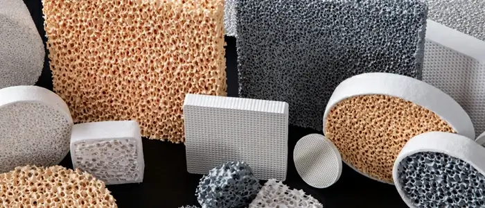
A ceramic foundry filter is a porous refractory structure placed in the gating system through which molten metal passes before entering the mold cavity. These filters are manufactured from high-purity oxide ceramics and feature an open-cell, three-dimensional structure that traps inclusions while allowing clean metal to flow through.
Key Functions
Ceramic filters serve two primary purposes:
- Filtration: Physically removing non-metallic inclusions from the melt
- Flow modification: Reducing turbulence and promoting laminar flow
Common Filter Materials
| Material | Temperature Limit | Best Applications | Key Characteristics |
|---|---|---|---|
| Alumina (Al₂O₃) | Up to 1100°C | Aluminum and its alloys | Good refractoriness, cost-effective |
| Silicon Carbide (SiC) | Up to 1500°C | Cast iron, copper alloys | High thermal conductivity, excellent strength |
| Zirconia (ZrO₂) | Up to 1700°C | Steel, superalloys | Partially stabilized for highest demands, thermal shock resistance |
| Alumina-Silicate | Varies | General purpose | Balance of refractoriness and inclusion affinity |
Zirconia-based filters, particularly partially stabilized zirconia (PSZ), are often used for the most demanding applications. Depending on the manufacturing process, they are available in two colors (white and tan/orange).
How Ceramic Foam Filters Work
Ceramic foam filters operate through four primary purification mechanisms:
Floating Separation Mechanism
When a ceramic foam filter is placed in the pouring system, it increases resistance to molten metal flow. This causes the liquid metal in the gating system to become full, enabling the slag-blocking function of the system. As liquid flow is throttled through the filter, metal briefly stays in the sprue, allowing lower-density slag to float up and separate—producing the same effect as a bottom-injection pouring system.
“Cake Filter” Mechanism
The curved channels of ceramic foam filters enable efficient mechanical slag blocking. Inclusions larger than the filter pores are captured at the inlet end. As captured inclusions accumulate, they form a “filter cake” on the inlet surface. This cake thins the liquid flow, allowing inclusions smaller than the filter pores to also be partially captured.
Adsorption Mechanism
When the first strand of molten metal arrives at the filter’s inlet surface, adsorption occurs between the liquid flow and the foam mesh. Under pressure, some inclusions become attached to the solid ceramic mesh frame due to what researchers describe as a “common grid correspondence” relationship. This is primarily non-selective, multi-molecular layer physical adsorption—inclusions build up layer by layer until blockage occurs.
Rectification Effect
As molten metal flows through the ceramic foam filter, it is divided into many small stream units. Their small diameter reduces the Reynolds number, causing the liquid flow to tend toward laminar flow. When metal flows laminarly—and because molten metal density greatly exceeds inclusion density—inclusions have sufficient time to float out and be removed.

The Reynolds Number Connection
Understanding the Reynolds number is crucial to appreciating filter value. The Reynolds number (Rn) is the ratio of inertial forces to viscous forces in a fluid. It distinguishes between:
- Laminar flow: Rn < 2000
- Unstable transition: Rn 2000-4000
- Turbulent flow: Rn > 4000
Why does this matter? Research shows that at an impact velocity of approximately 5 m/s of poured metal into a standing liquid bath, a 1:1 ratio of liquid volume to entrained air was determined. This entrained air introduces oxygen, leading to reoxidation inclusions.
By reducing flow velocity and promoting laminar flow, ceramic filters directly address this contamination source.
Types of Ceramic Foundry Filters
By Structure
1. Ceramic Foam Filters
The most common type, featuring a three-dimensional open-cell structure resembling foam. These lightweight filters offer high porosity (75-90%) and excellent flow characteristics.
Advantages:
- High porosity allows excellent flow with effective filtration
- Lightweight and easy to handle
- Distributes metal flow evenly, reducing turbulence
- Significantly improves casting quality and surface finish
Limitations:
- Single-use in most applications
- Performance depends on pore size selection
- Potential for “filter bits”—small particles that may detach if not properly sintered
2. Cellular (Extruded) Filters
These feature a geometric array of parallel channels separated by thin porous walls—like a honeycomb structure.
Advantages:
- High structural strength with minimal material
- Efficient flow distribution and low resistance
- Precise control over channel geometry
- Dimensional and structural consistency from filter to filter
Limitations:
- Vulnerable to channel blockage if pre-filtration is inadequate
- More complex manufacturing process
Flow-Rite® cellular filters from CoorsTek exemplify this technology, with cell densities ranging from 10ppi/100csi to 30ppi/300csi.
By Shape
| Filter Type | Shape | Best Applications |
|---|---|---|
| Disc Filters | Circular | Gravity die casting, low-pressure casting, aerospace components |
| Square Filters | Rectangular | Sand casting, permanent mold casting, large-section castings |
| Cylindrical Filters | Tube-shaped | Investment casting, titanium processing, high-value aerospace alloys |
| Filter Boxes | Rectangular/Custom | Ladle pouring systems, tapping troughs, continuous casting |
By PPI Rating
Filters are classified by Pores Per Inch (PPI), which enables estimation of capacities and flow rates depending on the metal. Common ranges include:
- 10 PPI: Coarse filtration, high flow rates—for large castings, high-throughput applications
- 20 PPI: Medium filtration—general purpose
- 30 PPI: Fine filtration—aerospace, critical components
PPI classification is traditionally performed visually by specially trained personnel using comparative standards (retainers)—a manual procedure that has proven sufficiently accurate for many years.
Key Technical Specifications
Filtration Pore Size
Pore size typically ranges from 20 to 100 µm (micrometers).
- Smaller pores (20–30 µm) : Superior filtration efficiency for high-precision applications (aerospace, automotive)
- Larger pores (60–100 µm) : Higher flow rates where throughput is prioritized
Porosity
Porosity refers to the percentage of open pore volume within the ceramic structure, typically 70% to 90%. Higher porosity allows greater metal throughput and reduced pressure drop, minimizing turbulence and reoxidation risk.
Thermal Stability
Ceramic filters must maintain structural integrity at extreme temperatures:
- Maximum working temperature: Up to 1700°C for zirconia filters
- Maximum recommended pouring temperature: 1470°C / 2680°F
- Maximum suggested pouring time: 60 seconds
Thermal Shock Resistance
Quality filters demonstrate exceptional thermal shock resistance. Zirconia filters, for example, can withstand ≥7 cycles under ΔT > 1000°C without fracture.
Strength Properties
- Compressive strength: 1.2 – 1.6 MPa for zirconia filters
- Filters must withstand physical stresses during shipping, handling, and molten metal flow
Filtration Efficiency
Premium filters achieve ≥80% inclusion removal efficiency for particles below 10 µm. Flow rate performance can exceed 8 L/min·cm², supporting high-throughput casting .
Proper Filter Selection
Step 1: Match Filter to Alloy
| Alloy | Recommended Filter Material | Notes |
|---|---|---|
| Aluminum | Alumina, Alumina-Silicate | Temperatures up to 1100°C |
| Magnesium | Alumina | Similar to aluminum requirements |
| Copper Alloys | Silicon Carbide | Up to 1500°C |
| Gray Iron | Silicon Carbide | 3:1 minimum area ratio |
| Ductile Iron | Silicon Carbide, Zirconia | 5:1 minimum area ratio |
| Steel | Zirconia | Up to 1700°C, partially stabilized |
| Superalloys | Zirconia | Highest temperature demands |
Step 2: Determine Required PPI
- 10-20 PPI: Large castings, high flow rates, coarse inclusions
- 20-30 PPI: General purpose, balanced flow and filtration
- 30+ PPI: Critical components, fine inclusions, lower flow rates
Step 3: Calculate Filter Area
The runner system’s choke—not the filter—should limit flow rate. The total usable filter area must be larger than the system choke.
Minimum Recommended Ratios:
- 3:1 for gray iron
- 4:1 for aluminum and copper-based alloys
- 5:1 for ductile iron
Flow rates and total flow capacity vary with:
- Metallostatic head
- Metal temperature
- Metal cleanliness
- Metal composition
Step 4: Consider Application-Specific Requirements
- High-pressure die casting: Strength requirements, robotic placement
- Investment casting: Filter cups, integration with wax patterns
- Continuous casting: Exchangeable filter systems, reactive cleaning
- Large castings (>1200 kg): 3D printed filters offer advantages
Installation Best Practices
Preheating
Always preheat ceramic foam filters to 200–400°C before use to:
- Prevent thermal shock
- Reduce moisture content
- Avoid hydrogen pickup in reactive metals like aluminum and titanium
Placement
Filters should be positioned in the gating system to:
- Ensure full, pressurized flow through the filter
- Allow easy access for inspection
- Prevent filter floating or displacement during pouring
Sealing
Proper sealing around the filter prevents metal bypass. Use appropriate gaskets or seating materials compatible with your alloy and temperature.
Storage
Store filters in dry conditions:
- Moisture-proof packaging
- Protective lining to prevent mechanical impact
- Temperature-controlled environment when possible
Industry Applications
Aerospace Manufacturing
The aerospace industry demands the highest standards of material purity. Aluminum and titanium alloys used in turbine blades, engine housings, and structural components require:
- Fine pore sizes (10–30 PPI)
- Investment casting integration
- Compliance with ASTM and AMS specifications
- Removal of inclusions that could cause micro-cracks
Automotive Industry
Engine blocks, transmission cases, suspension components, and brake calipers benefit from filtration through:
- Improved yield rates
- Reduced gas porosity
- Enhanced machinability
- Consistent quality in high-volume production
Heavy Equipment and Large Castings
For large castings (>1200 kg), 3D-printed filters offer particular advantages in flow capacity and consistency.
Electrical and Power Systems
High-conductivity copper and aluminum alloys for busbars and electrical enclosures require clean metal to maintain electrical and thermal conductivity.
Quality Control and Testing
PPI Classification
Filters are classified by PPI visually, using comparative standards—a manual procedure that has proven sufficiently accurate for many years.
Additional Testing Methods
- Weight checks: Ensure consistent density
- Impingement testing: Obtain precise flow data
- X-ray tomography: Examine internal structure
- Cold compression testing: Verify mechanical strength
Manufacturing Consistency
Traditional ceramic foam filters depend on the quality of phenolic urethane foams. Despite controls, structures may be present that negatively influence filtration efficiency—including thin, interrupted webs, non-uniform structures, and variable pore sizes. The smallest particles (“filter bits”) may detach during pouring.
The Future—3D Printed Ceramic Filters
Limitations of Traditional Foam Filters
The production of ceramic foam filters can result in structures that favor filter bit formation, compromising melt purity. Shrinkage during firing can reach up to 20%, making dimensional tolerance compliance challenging.
The 3D Printing Advantage
3D-printed filters (such as ASK Chemicals’ EXACTPORE®) offer:
- Exact reproducibility: Identical structure every time
- Consistent flow properties: Every filter performs identically
- Significant reduction of filter bits: No detached particles
- Improved flow behavior: Precisely controlled pore sizes
- Increased filter capacities: Higher throughput
- Design freedom: Custom geometries, anti-tipping features
- Better simulation options: CAD-based modeling
Real-World Results
A medium-sized steel foundry testing 75mm and 150mm zirconia filters (10 PPI) achieved 33% and 38% reductions in post-processing effort compared to conventional foam filters—a significant economic advantage.
New Possibilities
3D printing enables solutions previously impossible:
- Anti-tipping features: Additional edges prevent filter displacement during pouring
- Custom pore sizes: Precisely set for each application
- Adapt filters to castings: Rather than adapting castings to filters
Conclusion
Ceramic foundry filters are essential tools for modern metalcasters seeking to improve quality, reduce scrap, and increase profitability. By understanding the different types, materials, and selection criteria—and by staying informed about emerging technologies like 3D-printed filters—foundries can optimize their filtration systems for maximum benefit.
Whether you’re casting aluminum automotive components, steel valves, or superalloy aerospace parts, the right ceramic filter will deliver cleaner metal, better mechanical properties, and more consistent results.
Frequently Asked Questions
Do I need to preheat ceramic filters?
Yes, preheating to 200-400°C prevents thermal shock and removes moisture.
What’s the difference between PPI and pore size?
PPI (Pores Per Inch) describes the cell density; actual pore opening size varies by manufacturer but typically ranges from 20-100 µm.
Can I reuse ceramic foam filters?
No—ceramic foam filters are single-use in most applications. The captured inclusions block pores, and thermal cycling degrades the structure.
How do I select the right filter size?
Calculate based on your system choke area, using the minimum ratios: 3:1 for gray iron, 4:1 for aluminum/copper, 5:1 for ductile iron.
What causes filter breakage?
Common causes include thermal shock (inadequate preheating), mechanical overloading (exceeding filter capacity), and poor placement.
Are 3D-printed filters better than traditional foam?
For applications requiring consistency, high flow rates, and elimination of filter bits, 3D-printed filters offer significant advantages—demonstrated by 33-38% post-processing reductions in steel foundry trials.