


Shrinkage porosity is one of the most persistent and costly defects in metal casting. It occurs when the natural volume contraction of metal during solidification cannot be adequately compensated by liquid metal feed. The result is a network of voids—often jagged and interconnected—that compromises the structural integrity, pressure tightness, and fatigue life of cast components.
In aluminum castings alone, shrinkage and gas porosity are estimated to account for approximately 35% of total defects in high-pressure die-cast components. For foundries serving demanding industries such as automotive, aerospace, and oil and gas, understanding and controlling shrinkage porosity is not optional—it is essential.
What Is Shrinkage Porosity?
In metal castings, two primary types of porosity are identified: shrinkage porosity and gas porosity.
-
Shrinkage porosity occurs when the volume reduction accompanying solidification cannot be compensated by liquid metal feeding. The voids are typically irregular, jagged, and interconnected, often concentrated in the thickest sections or at sharp internal corners.
-
Gas porosity occurs when the gas concentration in the liquid metal exceeds its solubility, causing gas to precipitate out during solidification.
In practice, these two mechanisms often interact. Inadequate feeding causes a local pressure drop, which makes dissolved gas more supersaturated, leading to earlier formation of gas porosity. It is the interplay of these mechanisms that gives rise to porosity in a casting.
Shrinkage porosity can be classified by its morphology:
-
Linear/feathery shrinkage – elongated, filament-like voids
-
Sponge shrinkage – dispersed, porous regions
-
Combined shrinkage – a mixture of both types
The Formation Mechanism
The Physical Basis
Most cast metals have a lower density in the liquid state than in the solid state. This means that as the metal solidifies, it occupies less volume. If this volume reduction is not compensated by additional liquid metal flowing into the solidifying region, voids will form.
The fundamental mechanism of shrinkage porosity formation involves the mushy zone—the region between completely liquid and completely solid metal where dendrites are growing. As solidification proceeds:
-
Dendrites grow and begin to interlock
-
Fluid flow through the mushy zone becomes restricted
-
A pressure drop develops from the dendrite tips to the dendrite roots
-
When the pressure falls below a critical value, a pore nucleates and grows
The Role of Temperature Gradients
Shrinkage porosity is strongly influenced by the time-varying temperature profiles inside the solidifying casting. Temperature gradients determine whether a region that is just solidifying has access to sufficient feed metal at a higher temperature. Poor temperature gradients—where hot spots form in isolated regions—create “liquid pools” that become cut off from the feeding system. These isolated pools solidify last, and without a source of feed metal, they develop shrinkage cavities.
Main Causes of Shrinkage Porosity
Design-Related Causes
| Cause | Description |
|---|---|
| Non-uniform wall thickness | Thick sections solidify last and act as hot spots, creating isolated liquid pools |
| Abrupt section changes | Sharp transitions between thick and thin sections disrupt directional solidification |
| Insufficient taper | Lack of proper taper can prevent directional solidification |
| Inadequate riser design | Risers that are too small, incorrectly located, or improperly shaped cannot provide adequate feed metal |
Process-Related Causes
| Cause | Description |
|---|---|
| Low pouring temperature | Reduces the time available for liquid metal to feed before solidification completes |
| Excessive pouring temperature | Can cause bridging of columnar dendrites, creating large shrinkage porosities |
| Gate too thin | Restricts pressure maintenance and feed metal flow |
| Metal pressure too low | Insufficient pressure to drive liquid metal into solidifying regions |
| Incorrect mold conditions | Affects cooling rates and solidification front progression |
Material-Related Causes
Different alloys have different shrinkage characteristics:
-
Steels exhibit significant shrinkage and can develop high stresses due to their great shrinkage
-
Aluminum alloys are particularly susceptible due to the combination of solidification shrinkage and hydrogen gas evolution
-
Cast irons can develop shrinkage porosity when phosphorus content exceeds approximately 0.20%
Prevention Strategies and Best Practices
Riser (Feeder) Design
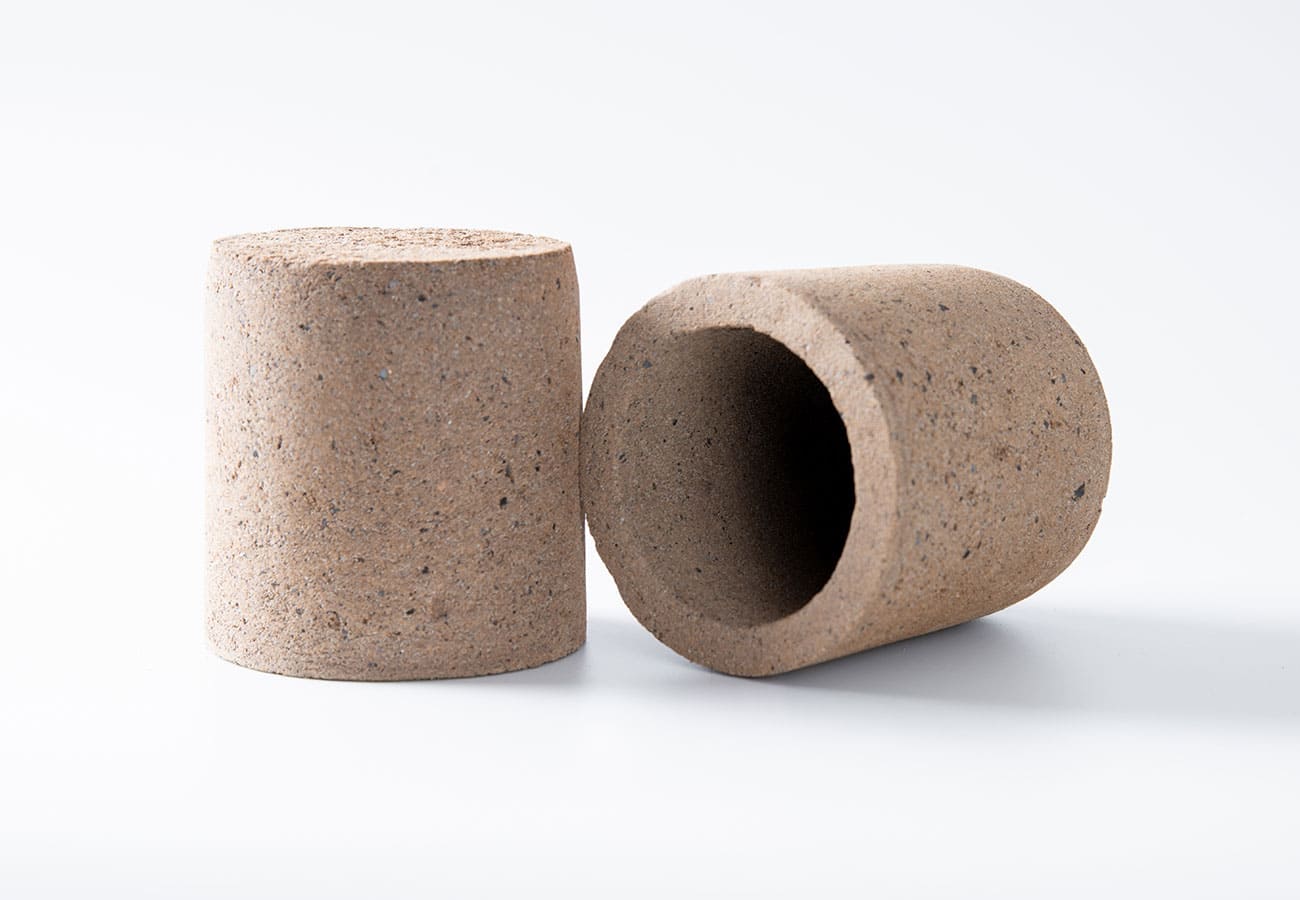
Risers serve as reservoirs of molten metal that feed into the casting to prevent porosity forming in isolated sections during solidification. Proper design of riser location, number, and size is critical.
Key principles:
-
Risers should feed into the heavy sections of the casting, which are the last to solidify
-
Risers must solidify after the section they are feeding
-
The riser neck must remain open until feeding is complete
Recent innovations: Research on 3D sand-printed riser geometries has shown significant improvements. Spherical risers were found to provide 45% yield improvement across multiple alloys (nickel aluminum bronze, low-carbon steel A216 WCB, and aluminum alloy A319), with riser neck diameter reductions of up to 77% compared to conventional designs.
Chills
Chills are metal inserts placed in the mold to accelerate cooling in specific regions–. They are used to:
-
Eliminate hot spots by promoting faster solidification
-
Create favorable temperature gradients for directional solidification
-
Prevent shrinkage porosity in areas where risers cannot be placed
Studies have shown that the addition of chills can reduce shrinkage porosity and hot tearing by more than 95% in optimized designs–. Chill thickness typically ranges from 25mm to 35mm depending on the application.
Taper and Geometry Optimization
The implementation of taper—small angled additions of mass on the boundaries of the part design—can reduce or eliminate regions of shrinkage porosity before risers are even placed. This approach addresses the root geometric causes of hot spots.
Gating System Design
The gating system must be designed to:
-
Promote directional solidification from the farthest points toward the risers
-
Maintain adequate metal pressure throughout solidification
-
Avoid turbulent filling, which can entrain oxides and bifilms
Research has shown that top and side filling gating systems repeatedly exhibit less shrinkage porosity and improved tensile properties compared to bottom filling systems. Interestingly, tranquil filling alone did not reduce overall shrinkage porosity–—the key is proper feeding, not just gentle filling.
Process Parameter Control
Pouring temperature must be carefully controlled. Both too low and too high can cause problems:
-
Too low: premature solidification cuts off feeding
-
Too high: can cause bridging and increased shrinkage
Mold condition and sand type affect cooling rates and must be selected to support the desired solidification front. Different sands result in different cooling rates, making it imperative to understand and control the process.
Exothermic Materials
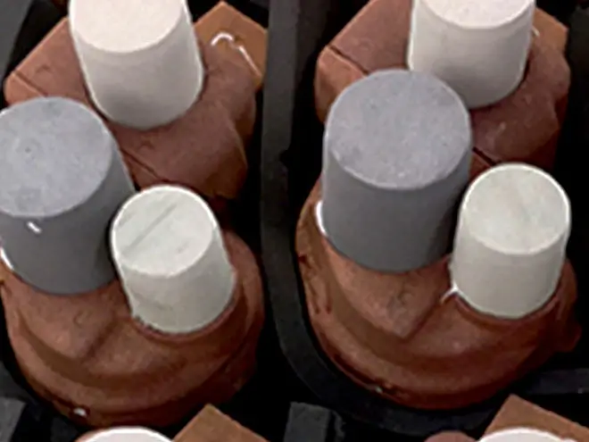
Exothermic materials applied to risers and sprue after pouring help retain heat and extend the solidification time of the riser, ensuring it remains liquid longer than the casting section it is feeding. However, careful selection is required—one foundry reported that changing to a new exothermic riser sleeve on a low-scrap job created numerous surface shrinkages, which were only resolved after additional solidification modeling and design tweaks.
Alloy Composition Control
For specific alloys:
-
Aluminum alloys: hydrogen content must be controlled to prevent the combined effect of shrinkage and gas porosity
-
Cast irons: phosphorus content should be kept below approximately 0.20% to avoid shrinkage porosity
-
Grain refinement: must be optimized—adding grain refiner beyond an optimum level can actually accentuate shrinkage defects
Prediction and Detection
Simulation and Modeling
Numerical simulation has become the preferred method for analyzing and predicting shrinkage porosity, enhancing process efficiency and minimizing trial-and-error experiments.
The Niyama Criterion is one of the most widely used prediction tools. It uses the thermal gradient (G) and cooling rate to identify regions at risk of shrinkage porosity. All regions in a casting with Niyama values below the critical value are likely to have shrinkage porosity–.
More sophisticated simulation tools like ProCAST incorporate advanced models that allow detailed calculations of shrinkage cavity formation.
Emerging technologies:
-
Machine learning-driven models can simulate dynamic shrinkage behavior during solidification, offering a low-cost, high-efficiency method for reducing shrinkage defects
-
Digital twin models integrating Reduced Order Models and machine learning can achieve real-time temperature prediction within 20°C accuracy and rapid shrinkage porosity distribution prediction
Quality Inspection
Shrinkage porosity is typically detected through:
-
Radiographic testing (RT) – reveals internal shrinkage cavities
-
Ultrasonic testing – detects internal discontinuities
-
Liquid penetrant testing – for surface-connected porosity
Industry standards such as MSS SP-55 and ASTM A802 provide visual quality standards that allow for some levels of acceptable shrinkage and gas porosity.
Shrinkage Allowances by Metal Type
When designing patterns, shrinkage allowances (patternmaker’s shrinkage allowances) must be incorporated to compensate for solidification contraction–. Typical allowances range from about 10 mm/m to 20 mm/m (1/8 in./ft to 1/4 in./ft).
| Material | Typical Shrinkage Allowance |
|---|---|
| Gray iron | ~1.0% |
| Steel | ~2.0% |
| Aluminum | ~1.5% |
| Manganese steel | ~2.6% |
| Brass | 1.3% – 1.55% |
Note: Thicker castings generally shrink somewhat less than thinner castings.
Summary of Best Practices
| Category | Best Practice |
|---|---|
| Design | Maintain uniform wall thickness; use coring to eliminate heavy sections |
| Riser design | Size and position risers to feed last-solidifying regions; consider 3D-optimized geometries |
| Chills | Use chills (25-35mm thickness) to eliminate hot spots and promote directional solidification |
| Gating | Design for directional solidification; top/side filling preferred over bottom filling |
| Temperature | Control pouring temperature within optimal range for the alloy |
| Alloy | Control composition (hydrogen in Al, phosphorus in cast iron, grain refinement levels) |
| Simulation | Use Niyama criterion and advanced simulation tools to predict and prevent defects |
| Quality | Inspect using radiographic or ultrasonic testing to standards such as MSS SP-55 and ASTM A802 |
Conclusion
Shrinkage porosity remains one of the most significant challenges in metal casting, but it is also one of the most preventable. By understanding the fundamental mechanisms—the role of the mushy zone, pressure drops, and temperature gradients—foundries can systematically address the root causes through careful design of risers, chills, gating systems, and process parameters.
The integration of advanced simulation tools, from the Niyama criterion to machine learning-powered digital twins, has dramatically improved the ability to predict and prevent shrinkage porosity before the first casting is poured. Combined with rigorous process control and quality inspection, these best practices enable foundries to consistently produce high-integrity, defect-free castings for even the most demanding applications.