

In metal casting, the runner and gate system serves as the final pathway through which molten metal enters the mold cavity. Their design directly determines whether the filling process will be smooth and controlled or turbulent and defect-prone. Turbulence during mold filling is a primary cause of gas porosity, oxide inclusions, and surface defects—problems that compromise mechanical properties and lead to costly scrap.
This article provides a comprehensive guide to optimizing runner and gate design specifically to minimize turbulence and the porosity it creates. Drawing on fluid dynamics principles, simulation studies, and practical foundry experience, we explore actionable strategies for achieving tranquil mold filling.
Understanding the Turbulence-Porosity Connection
Before examining optimization techniques, it is essential to understand how turbulence generates porosity.
The Mechanism of Gas Porosity
When molten metal flows turbulently, it entrains air and mold gases into the bulk liquid. These gas bubbles become trapped as the metal solidifies, creating porosity. In high-pressure die casting, where metal is injected at high velocity, this effect is particularly pronounced.
Research on magnesium alloy die casting demonstrates that gas porosity directly correlates with turbulent flow patterns and the fluid’s inability to push gas bubbles away from the main casting. X-ray analysis confirms that porosity tends to concentrate in regions where flow is most disturbed.
The Critical Velocity Threshold
Campbell’s research established that a critical velocity exists—approximately 0.5 m/s—above which the molten metal surface becomes unstable, folding over and entraining oxide films (bifilms) into the bulk liquid. These bifilms not only create porosity but also act as crack initiation sites that weaken the finished casting.
Design implication: Gate velocities should ideally remain below 0.5 m/s for oxidation-sensitive alloys, with absolute maximums of 1.0 m/s for more forgiving materials.
Optimizing Runner Geometry
The runner distributes metal from the sprue to the gates. Its geometry profoundly influences flow behavior and turbulence generation.
Eliminate Sharp Corners
Sharp corners in runners are a major source of air entrapment. When flow encounters a sharp corner, it separates from the wall, creating a low-pressure region that draws in air and generates turbulence.
Optimization rule: Runners must have smooth, rounded corners throughout their length. This maintains attached flow and minimizes air entrainment.
Maintain Decreasing Cross-Sectional Area
In pressurized systems (typical for die casting), the runner should have an ever-decreasing area from the plunger to the gate. This maintains metal velocity and ensures the runner remains full, preventing aspiration.
However, for unpressurized systems (preferred for oxidation-sensitive alloys), the runner area may expand after the choke to reduce velocity before the gates.
Avoid Abrupt Area Changes
Any sudden expansion or contraction in the runner creates turbulence. Small-to-large area changes cause flow separation and vortex formation, entraining air that becomes porosity somewhere in the casting.
Optimization rule: All area transitions should be gradual and streamlined.
Consider Runner Shape Optimization
For magnesium alloy die casting, research demonstrates that modifying runner shape significantly affects gas volume in the final casting. CFD simulations using the VOF (Volume of Fluid) method show that optimized runner geometries can reduce entrapped gas by improving flow patterns and maintaining fluid momentum.
Gate Design Optimization
The gate is where metal finally enters the cavity—and where turbulence is most likely to occur.

Gate Thickness Selection
Gate thickness has a direct impact on flow behavior and gas entrapment:
-
Thin gates: Reduce filling time by requiring less molten metal during the slow shot phase. However, they may not maintain fluid force effectively.
-
Thick gates: Better preserve fluid momentum within the runner and transmit it into the cavity, resulting in reduced gas volume.
Research confirms that gas volume correlates with gate thickness—thicker gates generally produce less porosity when properly designed.
Gate Velocity Control
Excessive gate velocity is perhaps the single most important factor in turbulence-related defects. A case study on gray iron castings found that reducing average gate velocity from 0.57 m/s to 0.49 m/s (and peak velocities from 1.47 m/s to 0.64 m/s) achieved an 80% reduction in scrap rate.
Optimization rule: Design gates with sufficient cross-sectional area to maintain velocity below critical thresholds. For high-pressure die casting, MAGMASOFT simulations can determine the optimal second-phase velocity that minimizes air entrapment while avoiding misruns.
Gate Positioning
Gate location dramatically affects flow patterns and air entrapment:
-
Vertical gating: A case study on zinc die casting demonstrated that modifying the design to allow vertical gating along a column significantly reduced air entrapment and entrainment compared to horizontal filling. This improvement was verified through flow simulations during the tooling design process.
-
Multi-gate configurations: For complex parts, multiple gates may be necessary. MAGMASOFT optimization studies on an ADC12 crossbeam compared four gating layouts and found that a configuration with five smaller gates generated approximately 10% less melt surface area during filling than the worst alternative. Less melt surface area means less air entrainment and lower porosity.
-
Gate positioning for flow balance: Research on magnesium alloy die casting demonstrates that optimizing runner and gate positioning generates balanced velocity and temperature distribution inside the mold cavity. This balance improves solidification patterns and reduces casting defects.
Specialized Components for Turbulence Reduction
Beyond basic geometry optimization, several specialized components can dramatically reduce turbulence.
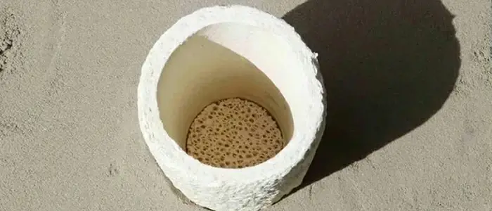
Filters
Ceramic filters serve two critical functions in turbulence reduction:
-
Velocity reduction: Filters break the flow into smaller streams, reducing velocity and turbulence
-
Bubble diversion: When placed flush on top of the runner, filters act as bubble diverters, preventing air from entering the cavity
Research comparing three non-pressurizing bottom-gating systems found that designs incorporating filters significantly reduced flow kinetic energy, avoided surface turbulence, and produced castings with fewer defects and higher reliability.
Surge Wells (Spin Traps)
A surge well (or “surge”) added at the end of the runner serves as a terminal spin trap that captures the first, dirtiest metal and dissipates flow energy.
Remarkably, research demonstrates that appropriate use of a surge in the running system can be as effective as employing a filter in reducing melt front velocity. This finding provides foundries with design flexibility—both approaches effectively reduce turbulence.
Naturally Pressurized Systems
Traditional steel casting systems using preformed refractory tubes often behave poorly in terms of turbulence control. However, naturally pressurized filling systems—designed with careful attention to flow continuity and pressure distribution—demonstrate excellent performance in simulation and practical application.
Bubble Traps
Advanced systems like the trident gate incorporate bubble traps and multiple filters to achieve unprecedented defect reduction. Simulation confirms that these designs outperform all alternatives, capable of producing defect-free castings routinely.
The Critical Role of Ejector Pins
While often overlooked, ejector pins in the runner system can be significant sources of turbulence.
The Problem
High or low ejector pins disrupt the smooth flow path, creating obstructions that generate air entrapment. Even a slightly low ejector pin adds porosity to the casting somewhere—the only question is whether it creates a quality issue for that particular part.
The Solution
Ejector pins must be perfectly flush with the runner surface. Any deviation—high or low—creates turbulence and should be eliminated. X-ray imaging of castings with runners attached can reveal bubbles coming from trapped air locations, helping identify problematic pins.
Simulation-Based Optimization
Modern foundry practice increasingly relies on computational fluid dynamics (CFD) simulation to optimize runner and gate designs before cutting tooling.
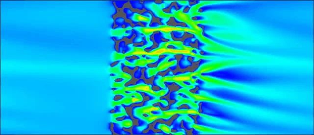
What Simulation Reveals
Casting simulation programs (FLOW-3D, MAGMAsoft, JSCAST, etc.) can predict:
-
Flow patterns and velocity distribution
-
Air entrainment and gas porosity locations
-
Temperature distribution during filling
-
Solidification sequences
-
Melt surface area generation (a key indicator of air entrainment)
The MAGMA Approach Case Study
A compelling example involves an ADC12 crossbeam die casting. Using MAGMASOFT’s autonomous engineering capabilities:
-
Four gating layouts were evaluated based on “Smooth Filling”—an optimization objective that minimizes total melt surface area generated during filling
-
Layout A (five smaller gates) showed the best result with approximately 10% less melt surface area than the worst concept
-
First iteration revealed high air pressure indications in a critical region
-
Second iteration added additional venting, solving the problem
-
Virtual Design of Experiments (DoE) optimized second-phase velocity between 3.5-4.0 m/s to minimize air entrapment while preventing misruns
The result: First-shot production success with high-integrity castings confirmed by X-ray inspection and subsequent welding tests. This systematic approach shortened development time and avoided costly tooling modifications.
Magnesium Alloy Optimization
For magnesium alloy die casting, researchers combined CFD simulation with experimental validation. X-ray analysis of sample products showed correlation between gas porosity and CFD results. Based on localized porosity positions, runner and gating systems were modified, and new designs were simulated to verify improvements before implementation.
Gate Thickness Optimization Using JSCAST
Japanese researchers used JSCAST simulation software to investigate runner shape effects on gas volume in magnesium alloy die casting. The three-dimensional numerical model, based on direct finite difference and VOF methods, revealed that gate thickness significantly influences gas entrapment—leading to the conclusion that thicker gates generally reduce gas volume.
Practical Checklist for Optimization
Based on the research and case studies reviewed, here is a practical checklist for optimizing runner and gate design to reduce turbulence and porosity:
| Design Element | Optimization Objective | Key Considerations |
|---|---|---|
| Runner corners | Eliminate sharp corners | All corners must be smooth and rounded |
| Area transitions | Gradual changes only | Avoid abrupt expansions/contractions |
| Ejector pins | Perfectly flush | Any high/low pin creates porosity |
| Gate velocity | Below 0.5-1.0 m/s | Lower for oxidation-sensitive alloys |
| Gate thickness | Sufficient for fluid momentum | Thicker gates generally reduce gas |
| Gate position | Strategic placement | Vertical gating reduces air entrapment |
| Filters | Include in design | Reduces velocity, diverts bubbles |
| Surge wells | Consider as alternative | Can be as effective as filters |
| Multi-gate balance | Ensure even distribution | Use simulation to verify |
| Simulation validation | Always simulate first | CFD essential for optimization |
Conclusion: The Path to Tranquil Filling
Optimizing runner and gate design to reduce turbulence and porosity requires a systematic approach grounded in fluid dynamics principles and validated by modern simulation tools.
The key takeaways from current research and practice:
-
Velocity control is paramount—maintaining gate velocities below critical thresholds prevents the surface turbulence that creates oxide films and entrains gas
-
Geometry matters at every scale—from major runner layouts to individual ejector pins, every geometric feature affects flow
-
Filters and surge wells—these components provide powerful tools for reducing flow energy and capturing defects before they enter the cavity
-
Simulation enables optimization—CFD tools allow multiple design iterations virtually, identifying optimal configurations before tooling commitment
-
Balanced flow is essential—multi-gate systems must distribute metal evenly to prevent localized turbulence and porosity
By applying these principles—and leveraging the demonstrated success of designs like the trident gate that produce defect-free castings routinely—foundries can significantly reduce turbulence-related defects, improve casting quality, and minimize costly scrap.