


Ceramic foam filters are engineered to deliver exceptional molten metal cleanliness, but even the highest quality filter can fail to perform if installed incorrectly. Improper installation leads to filter breakage, restricted metal flow, and compromised casting quality—directly impacting your foundry’s productivity and bottom line.
Why Proper Installation Matters
A properly installed ceramic foam filter does more than just trap inclusions. Research confirms that filters transform turbulent flow into laminar flow, significantly reducing re-oxidation within the mold and minimizing sand erosion risk. However, this only happens when the filter is correctly positioned and sealed.
| Problem | Likely Cause | Result |
|---|---|---|
| Filter cracks during pouring | Thermal shock from inadequate preheating | Fragments enter casting, causing inclusions |
| Metal bypasses filter | Poor sealing around edges | No filtration occurs |
| Filter floats or shifts | Improper fixation | Unfiltered metal enters mold |
| Slow mold filling | Filter area too small or wrong placement | Cold shuts, misruns |
| Premature clogging | Poor flow distribution | Reduced effective filtration area |
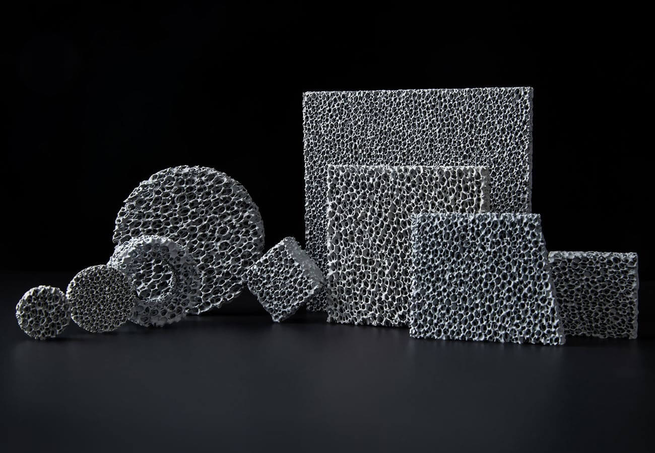
Step 1: Pre-Installation Inspection and Preparation
Inspect the Filter
Before installation, carefully inspect each filter for visible damage. Check that the filter has no visible cracks—use strong light to see through the filter for a thorough inspection. Even small chips or cracks can become failure points under thermal and mechanical load during pouring.
Clean the Pouring System
Remove impurities, dust, and any old filter materials from the pouring cup, pouring channel, and filter seat. Before using a ceramic foam filter, use compressed air to blow off surface dust and internal fragments to prevent impurities from contaminating the molten metal.
Verify Filter Dimensions
Confirm that the filter dimensions match the cavity in your gating system. The filter should fit snugly within the cavity with a recommended gap of no more than 1–2 mm per side. For standard filter sizing, 50 mm × 50 mm filters typically handle castings with total weights around 15 kg (including feeders and gating channels).
Pre-Drying (If Needed)
Filters are fragile products and should be handled with care to prevent damage. Avoid moisture during storage—store in a dry environment. If filters were exposed to high humidity during transportation or storage, they must be dried at 110°C before use until moisture is completely removed. Moisture in the filter can cause gases to be released during casting, leading to bubbling and floating.
Step 2: Choosing the Installation Location
General Principle
The filter should be placed as close to the casting cavity as possible to maximize filtration efficiency and flow conditioning, and to minimize the probability of secondary oxidation after filtration. Ideally, foam structure filters should be placed as close to the casting as possible.
Common Installation Positions
Ceramic foam filters can be placed at various points in the gating system:
1. In the Runner (Horizontal Placement) — This is the most common and recommended position. The filter is placed horizontally in the runner, allowing molten metal to pass vertically through it. This arrangement allows slag to float to the top surface of the runner, increasing the amount of molten metal that can pass before clogging.
2. At the Bottom of the Sprue — Sometimes filters are placed at the bottom of the sprue, but this is not recommended because the filtering effect and flow adjustment can be negatively affected by turbulent flow from the sprue bottom to the runner.
3. Under the Sprue Cup — Suitable for simple castings and easy to install, but may not protect the entire runner system.
4. Vertical or 45° Placement — Filters can also be placed vertically or at 45 degrees, depending on the specific situation and casting design.
Best Distance from Pouring Cup
The optimal distance from the pouring cup to the filter is 50–100 mm.
Avoid Direct Impact
Try to avoid molten metal directly impacting the filter screen. For direct impact situations, the pouring height should preferably not exceed 200 mm.
Step 3: Sizing the Filter Correctly
Filter Area vs. Choke Area Ratio
When designing the gating system for placing the filter, it must be ensured that the filling speed will not be reduced due to the filter. The filter should not be used as a blocking section.
At the runner where the filter is placed, the cross-sectional size of the runner should be appropriately enlarged. The filter working area should be 4 to 6 times the choke (blocking) section of the gating system–. This ensures that the pouring speed is not affected.
It is generally recommended to use a filter area/choke area ratio of at least four, but for thin-sectioned castings, the ratio should be higher. Finer pore sizes (e.g., 15 and 25 PPI) slightly increase the filter flow restriction and may require a slight increase in the filter area.
Recommended Ratio Reference
A commonly recommended ratio for the gating system sections is:
F sprue : F filter front-end : F filter back-end : F runner : F ingate = 1 : 4 : 1.75 : 1.1 : 1.2
Filter Thickness Selection
Filter thickness is important—if the filter is too thick, it increases system resistance and cost; if too thin, strength is insufficient. For large castings with long pouring times and significant metal drop height (which creates high impact force on the filter), thickness is typically selected at 30–40 mm.
Step 4: Filter Seat and Support Design
Filter Seat Requirements
The filter must be placed on a secure filter seat to make the installation convenient, firm, and reliable. There should be rounded corners on the mold support surface where the filter is placed to prevent sand washing.
Design Specifications
-
Inflow surface lap: 3–5 mm
-
Outflow surface support height: More than 5 mm
-
Gap around filter: 1–1.5 mm with sand collecting grooves
-
Upper surface height: 0.5–1 mm lower than the parting surface to prevent the filter from being crushed when the box is closed
-
Stepped filter seat: Adopt a stepped design to reduce bottom stress
-
Support surface flatness error: ≤ 0.5 mm
Special cast iron fixtures used with the filter must withstand 1300°C high temperature.
Step 5: Filter Placement and Sealing
Placing the Filter
-
Position the filter in the prepared seat within the gating system.
-
Ensure the filter sits perfectly horizontal and is fully seated in the prepared cavity.
-
Use a tool or guide to lower the filter straight down into the prepared seat.
Sealing
Proper sealing is critical to prevent metal bypass. If leakage occurs, the metal filtering effect will be reduced.
-
Use refractory mud or a ceramic fiber mat to fix the filter in place, ensuring stability and no gaps.
-
Apply a high-temperature ceramic fiber gasket paper or refractory paste around the filter’s edges before seating it—this creates a positive seal and prevents metal bypass.
-
Use an elastic sealing device or gasket-type seal to seal the filter plate in place.
-
The sealing material should surround the filter plate at the periphery.
-
Do not press too tightly on the filter plate with the sealing lining—when the filter plate is heated, stress generated by expansion of the sealing material can crack or break the filter plate.
Assemble the Pouring System
Assemble the pouring cup, pouring channel, and other components in sequence, ensuring that the filter is in the correct position. Make sure each connection is well sealed to prevent molten metal from leaking.
Step 6: Preheating—The Most Critical Step
Why Preheating Is Essential
Placing a cold filter into molten metal creates severe thermal shock. The dramatic temperature difference between a room-temperature filter and molten metal (e.g., 720°C for aluminum, 1450°C for iron) causes thermal stress that can crack or shatter the ceramic structure.
Proper preheating:
-
Prevents thermal shock cracking
-
Removes moisture that could cause gas defects
-
Opens filter pores (avoids occlusion from thermal expansion)
-
Ensures the filter reaches near-molten temperature for smooth flow initiation
Recommended Preheating Parameters
Based on extensive testing and field experience:
| Parameter | Recommendation |
|---|---|
| Preheating temperature | 600–800°C (adjusted according to filter size and alloy) |
| Preheating time | ≥ 30 minutes (large filters may need 1 hour) |
| Heating rate | ≤ 10°C per minute (avoid rapid heating that causes thermal stress) |
| Preheating method | Dedicated preheating furnace (safer than direct flame heating) |
A ceramic foam filter should have a minimum temperature of 550°C. Finer filters with porosity of PPI 50 and PPI 60 should have a higher preheating temperature of approximately 650°C.
Preheating Best Practices
-
Use a controlled oven: Direct flame creates hot spots and uneven heating.
-
Soak time matters: Ensure the filter core reaches temperature—30–45 minutes minimum for standard 50 mm thick filters.
-
Preheat the filter box too: The filter seat or box should also be preheated to match the filter temperature.
-
Temperature verification: If available, use a pyrometer to confirm temperature.
Special Note for Different Alloys
-
For aluminum casting: Preheat to at least 260°C is essential, though higher temperatures (closer to melt temperature) are better. Proper preheating allows the expanding sealing gasket to seal effectively and prevents molten aluminum from solidifying in the pores upon first contact. Preheating the filter bowl and ceramic foam filter evenly for 15–30 minutes ensures their temperature is close to molten aluminum.
-
For cast iron and steel: Higher preheating temperatures (600–800°C) are required due to the higher pouring temperatures.

Step 7: Installation Timeline
After preheating, installation should be completed within 10 minutes to prevent the filter from cooling down too much.
Step 8: Pouring Control
Recommended Pouring Parameters
| Metal Type | Recommended Pouring Speed | Maximum Impact Height |
|---|---|---|
| Aluminum alloy | 0.5–1.2 kg/s | ≤ 150 mm |
| Cast iron | 1.5–3.0 kg/s | ≤ 100 mm |
| Copper alloy | 0.8–1.8 kg/s | ≤ 120 mm |
Pouring Best Practices
-
Maintain an appropriate flow rate to avoid excessive shock to the filter.
-
Maintain 50% normal flow for 2–3 seconds during the first pouring to allow the filter to stabilize.
-
Observe the pouring process to ensure the filter works properly.
-
The pouring volume should be less than the recommended molten metal volume.
-
The pouring speed should be less than the recommended pouring speed.
Common Installation Mistakes to Avoid
Mistake 1: Inadequate or Uneven Preheating
The Error: Placing a cold or only partially warmed filter into the filter box or gating system before pouring.
The Consequences:
-
Instant cracking or shattering from thermal stress
-
Reduced flow rate as a cold filter chills the initial metal flow
-
Gas evolution from moisture or contaminants vaporizing
The Solution: Implement a strict, standardized preheating protocol as outlined in Step 6.
Mistake 2: Incorrect Fit and Lack of Sealing
The Error: Using a filter that is too small for the cavity, creating gaps around the edges, or forcing an oversized filter into place.
The Consequences:
-
Bypass flow—molten metal flows around, not through, the filter
-
Erosion and inclusion release from turbulent flow through gaps
The Solution: Ensure a precise, sealed fit with no more than 1–2 mm gap per side and always apply a high-temperature sealant.
Mistake 3: Improper Handling
The Error: Handling filters roughly (dropping, knocking them together) or placing them carelessly.
The Consequences:
-
Mechanical damage creating failure points
-
Uneven flow distribution leading to premature clogging
The Solution: Treat filters as precision components—handle with care, preferably wearing gloves.
Mistake 4: Casting onto an Overheated or Underheated Filter
The Error: Improper preheating temperature.
The Consequences:
-
Casting onto an overheated filter may cause rapid oxidation of the metal while priming, which may lead to filter blockage
-
If the filter is not properly preheated or the cast is started too early, metal may freeze inside the filter—once the metal is frozen, it will not remelt
The Solution: Follow the recommended preheating parameters precisely and verify temperature with a pyrometer.
Mistake 5: Filter Placed Too Far from the Casting
The Error: Placing the filter too far from the casting cavity.
The Consequence: Increased probability of secondary oxidation after filtration.
The Solution: Place the filter as close to the casting cavity as possible.
Storage and Handling Best Practices
-
Store in a dry, ventilated place, free from rain and heavy pressure.
-
Handle with care to prevent bumping and stepping—filters are fragile products.
-
Stacking: Cardboard boxes can be stacked, but no more than seven layers.
-
Shelf life: Maximum recommended shelf life is three years under optimal storage conditions.
-
If filters were exposed to high humidity, dry at 110°C before use until moisture is completely removed.
Troubleshooting Quick Reference
| Issue | Likely Cause | Solution |
|---|---|---|
| Filter cracks during pouring | Thermal shock from inadequate preheating | Increase preheating temperature to 600–800°C, ensure ≥30 min soak time |
| Metal bypasses filter | Poor sealing around edges | Apply refractory mud or ceramic fiber gasket, ensure gap ≤1 mm |
| Filter floats or shifts | Improper fixation | Use stepped filter seat, secure with refractory materials |
| Slow mold filling | Filter area too small | Increase filter area to 4–6× choke area |
| Premature clogging | Poor flow distribution | Ensure filter is level, check PPI rating matches application |
| Gas defects in casting | Moisture in filter | Dry filter at 110°C before use, ensure proper preheating |
Conclusion
Proper installation of ceramic foam filters is essential to ensure their filtering effect and extend their service life. By following this step-by-step guide—from careful inspection and proper sizing through correct placement, sealing, and preheating—you can maximize filtration efficiency, reduce casting defects, and significantly improve your foundry’s productivity and profitability.
With correct installation, silicon carbide ceramic foam filters that have undergone special thermal shock treatment can see their service life increased by up to 40%.
For installation guidance videos or on-site technical support, please contact our engineering team.
📧 Email: info@sf-foundry.com
📱 WhatsApp: 8618636913699