


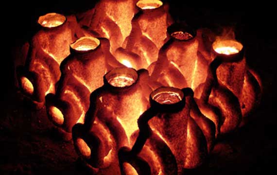
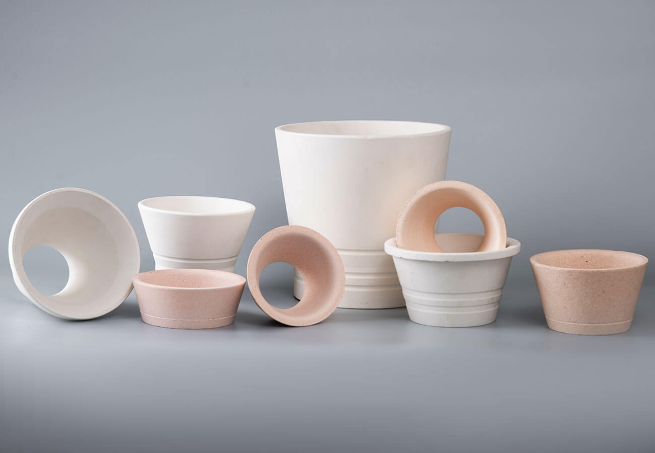
The wax tree assembly is one of the most critical stages in the investment casting (lost-wax casting) process. During this stage, individual wax patterns are attached to a central wax gating system to form a tree-like assembly. The ceramic pouring cups — attached to the end of the main bars or sprues—serves as the entry point that will introduce molten metal into the mold.
A properly assembled pouring cup ensures smooth metal flow, reduces turbulence, and minimizes inclusions in the final casting. This guide provides a comprehensive, step-by-step approach to assembling ceramic pouring cups on wax trees.
Before You Begin: Preparation and Inspection
Step 1: Visually Inspect All Wax Models
Before any assembly work begins, visually inspect all wax patterns and components to ensure they are 100% qualified. Check for:
-
Surface defects such as cracks, voids, or flash
-
Dimensional accuracy against design specifications
-
Any distortion or warping
-
Non-fill of wax pattern or excess wax
Quality check tip: Reject any defective wax patterns immediately. A flawed pattern will produce a flawed casting, regardless of how carefully the rest of the process is executed.

Step 2: Select an Appropriately Sized Steel Flask
The steel flask (or investment container) must be selected based on the size of your wax tree assembly.
Clearance requirements:
-
Maintain at least one inch (25.4 mm) of clearance around your wax patterns
-
Ensure adequate clearance between the tip of the sprue and the top of the flask
Proper clearance is essential to allow the ceramic slurry to coat all surfaces evenly during the shell-building process. Tight spacing prevents ceramic slurry from fully coating the surfaces between patterns, leaving dry spots that can crack during dewaxing.
Step 3: Select the Runner Type and Inspect the Wax Runner
Select the appropriate runner type according to your casting process and technical regulations. Then:
-
Check the wax runner (die head) to ensure it is qualified
-
Verify that the runner is free from distortion or defects
Assembling the Pouring Cup on the Wax Tree
Step 4: Attach the Tree to the Base Board via the Pouring Cup
This is the foundational step of the assembly process.
Procedure:
-
Position the pouring cup at the end of the wax tree assembly (the sprue, gate pattern assembly).
-
Attach the entire tree to a piece of masonite or plywood by the pouring cup.
-
Melt the pouring cup onto the board so it firmly sticks.
-
Select a board with a rough surface—masonite works best as it provides superior adhesion.
Why this matters: The base board provides stability during the shell-building process. The pouring cup, being the lowest point of the tree in this orientation, serves as the attachment point that will later become the top entry point for molten metal.
Step 5: Install the Cover Plate on the Gate Cup
Procedure:
-
Install a cleaned cover plate on the gate cup of the qualified wax runner.
-
Ensure the cover plate is smooth and seamless.
-
If there is any gap between the cover plate and the gate cup, use an electric soldering iron to flatten the gap.
Why this matters: Any gap or seam allows ceramic slurry to flow into the shell during the dipping process, which can compromise the integrity of the ceramic mold.
Step 6: Weld the Wax Mold to the Runner
Procedure:
-
Use bonding wax or an electric soldering iron for welding.
-
Place the wax runner (die head) in position.
-
Weld the wax mold neatly and firmly according to technical regulations.
-
Stick the wax pattern securely onto the runner (die head).
-
Ensure all weld joints are firm and seamless.
Tools commonly used: hot wax knife (electric), artist brush, spatula, gas torch.
Common welding defects to avoid:
-
Distortion of the runner
-
Pattern flash
-
Poor finished surface
-
Wax droplets remaining on the wax mold (scrape them clean)
Step 7: Mark Identification on the Gate Cup
On the gate cup of the assembled wax module, mark an identification mark according to the metal material specified in the process.
Why this matters: This ensures traceability throughout the casting process. Different alloys may require different handling, pouring temperatures, or post-casting treatments.
Step 8: Place the Cylinder Around the Tree
Procedure:
-
Place the steel cylinder (flask) around the tree.
-
Ensure good clearance exists between the patterns and the flask wall.
-
Check that the clearance is consistent all around the assembly.
Step 9: Create a Wax Fillet Seal
Procedure:
-
Create a wax fillet on the outside of the flask, between the flask and the base board.
Method 1—Using a brush:
-
Dip a disposable 2-inch paint brush in molten wax.
-
Brush around the base of the flask to create a fillet.
Method 2—Without a brush:
-
Cut slivers of wax and melt them around the base.
-
Use a propane torch to hit the fillet and improve the seal.
Why this matters: The wax fillet seals the flask to the base board, preventing plaster or ceramic slurry from seeping out during the investment process.
Step 10: Apply Debubbler (Optional but Recommended)
Procedure:
-
Brush on some debubbler solution—essentially a soapy water mix.
-
This prevents air bubbles from sticking to the casting surface.
Why this matters: Air bubbles on the surface of your casting turn into metal warts when the casting is formed. While these can be removed after casting, it is better to prevent them from forming in the first place.
Step 11: Final Inspection and Cleanup
Procedure:
-
Use compressed air to blow off any wax chips on the module.
-
Inspect the entire tree for any defects.
-
Confirm alignment, positioning, and spacing of gates to corresponding patterns.
-
Rectify any issues prior to completion of tree assembly.
-
Inspect and examine the total tree for defects and rectify prior to completion.
Final quality checks:
-
All welds are firm and seamless
-
All wax patterns on the same module are of the same material
-
No wax droplets remain on any wax mold
-
All surfaces are uniform and smooth
Step 12: Transport to Next Stage
-
Hang the module on a transport cart.
-
Send to the mold washing (shell-building) process.
Visual Summary: Assembly Flowchart
| Step | Action | Key Tool/Equipment |
|---|---|---|
| 1 | Inspect wax patterns | Visual inspection |
| 2 | Select steel flask | Steel flask (appropriate size) |
| 3 | Inspect wax runner | Visual inspection |
| 4 | Attach tree to base board via pouring cup | Masonite/plywood + heat |
| 5 | Install cover plate on gate cup | Cover plate + electric soldering iron |
| 6 | Weld wax mold to runner | Bonding wax or electric soldering iron |
| 7 | Mark identification | Marking tool |
| 8 | Place cylinder around tree | Steel flask |
| 9 | Create wax fillet seal | Paint brush + molten wax / propane torch |
| 10 | Apply debubbler (optional) | Debubbler solution + brush |
| 11 | Final inspection and cleanup | Compressed air |
| 12 | Transport to shell-building | Transport cart |
Common Assembly Mistakes and How to Avoid Them
| Mistake | Consequence | Prevention |
|---|---|---|
| Gaps between cover plate and gate cup | Slurry enters shell during dipping | Flatten gaps with electric soldering iron |
| Inadequate clearance around patterns | Dry spots, shell cracking during dewaxing | Maintain minimum 10–15mm gap between patterns |
| Weak or incomplete welding | Patterns detach during shell building | Ensure all welds are firm and seamless |
| Wax droplets on molds | Surface defects in final casting | Scrape wax droplets clean |
| Mixed wax materials on same tree | Inconsistent melting and shell behavior | Use same material on same module |
| Poor wax fillet seal | Slurry leakage from flask | Create complete, smooth wax fillet around base |
| Air bubbles on surface | Metal warts on finished casting | Apply debubbler solution before investment |
Best Practices Summary
- Inspect before assembly – Never assemble defective wax patterns. Check every component before welding.
- Maintain proper clearances – Ensure adequate space around all patterns and between the sprue and flask top.
- Weld firmly and seamlessly – All joints must be secure and smooth to prevent slurry penetration.
- Use the right board – Masonite or rough-surfaced plywood provides the best adhesion for the pouring cup.
- Seal completely – The wax fillet is not optional; it prevents costly slurry leaks.
- Mark for traceability – Identification marks ensure proper alloy tracking throughout the process.
- Clean thoroughly – Remove all wax chips and droplets before proceeding to shell-building.
- Work safely – Use appropriate PPE: safety glasses, heat-resistant clothing, and protective footwear. Cut off power supply after work and maintain fire prevention practices.
From Assembly to Shell Building
Once the wax tree assembly is complete—with the ceramic pouring cup securely attached, all patterns welded, and the wax fillet sealed—the assembly proceeds to the shell-building (investing) stage.
The entire assembly is dipped repeatedly into a ceramic slurry and coated with progressively more refractory material. The ceramic pouring cup, now firmly attached to the tree, becomes an integral part of the ceramic shell. After the shell reaches the desired thickness, it is dried and hardened. The wax is then melted out in a dewaxing furnace, leaving behind a hollow ceramic mold with the pouring cup as the entry point for molten metal.
A properly assembled pouring cup—securely attached, seamlessly sealed, and correctly positioned—sets the foundation for a successful casting. As the saying goes in investment casting: quality doesn’t begin in the mold cavity; it begins at the cup.
All technical data and procedures presented are sourced from published industry references and standard investment casting practices. Actual procedures may vary depending on specific foundry equipment, casting requirements, and workplace quality procedures. Always follow your facility’s specific technical regulations and safety guidelines.