

If you cast aluminum, you know the problem: hydrogen porosity. Hydrogen gas dissolves readily in molten aluminum. When the metal solidifies, the hydrogen comes out of solution, forming tiny gas pores that ruin mechanical properties, machining characteristics, and pressure tightness.
The solution is degassing—introducing an inert gas (usually argon or nitrogen) into the melt to remove hydrogen and other impurities. And the most effective tool for degassing is the graphite degassing rotor.
This guide covers everything you need to know about degassing rotors: how they work, how to choose the right one, and how to keep it performing at its best.
Why Degassing Matters in Aluminum Casting
The Hydrogen Problem
Aluminum has a high affinity for hydrogen. In molten aluminum, hydrogen solubility is about 20 times higher than in solid aluminum. When the metal solidifies, the excess hydrogen forms gas porosity—tiny voids that:
| Consequence | Impact |
|---|---|
| Reduced mechanical properties | Lower strength, ductility, and fatigue life |
| Machining problems | Porous surfaces, poor finish |
| Leaks | Failure in pressure-tight components (valves, pumps, engine blocks) |
| Surface defects | Cosmetic issues, rework |
Sources of Hydrogen
| Source | How It Enters |
|---|---|
| Moisture in charge materials | Wet scrap, damp ingots |
| Atmospheric humidity | Absorbed by the melt |
| Oils and lubricants | From recycled scrap |
| Refractory moisture | From furnace lining or tools |
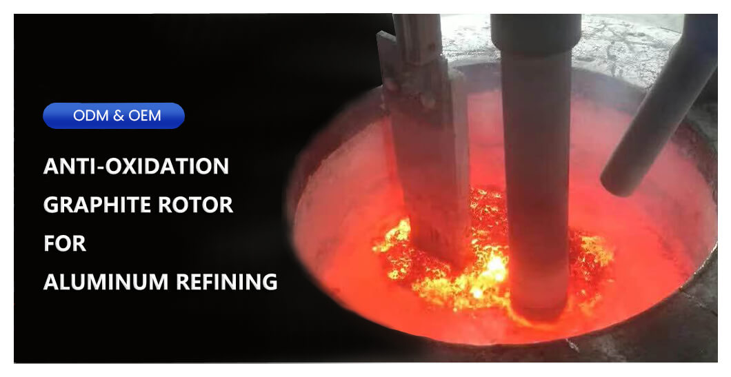
The Solution: Rotor Degassing
Rotor degassing uses a rotating graphite shaft with a specially designed impeller to inject inert gas into the melt. The rotor:
-
Breaks the gas into fine bubbles (large surface area for hydrogen diffusion)
-
Circulates the gas throughout the melt (not just locally)
-
Creates a flow pattern that brings hydrogen-rich metal to the gas interface
-
Helps float out non-metallic inclusions (oxides, carbides) as well
What Is a Degassing Rotor?
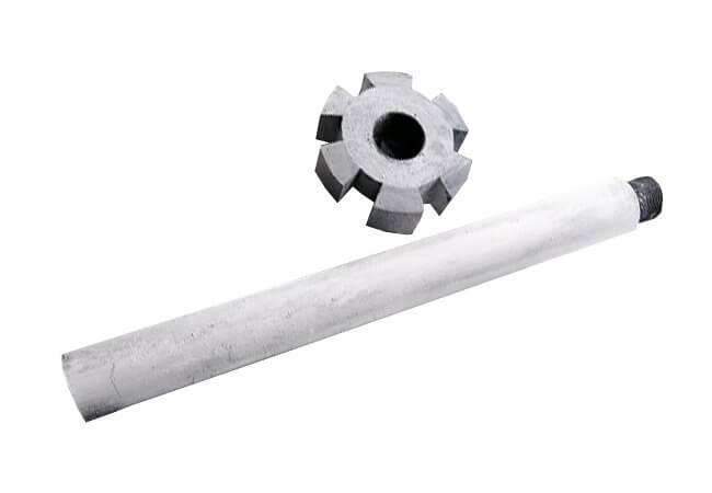
A degassing rotor is a graphite component designed to be immersed in molten aluminum while rotating and delivering inert gas.
Basic Components
| Component | Function |
|---|---|
| Shaft | Long graphite tube that transmits rotation and gas |
| Impeller (rotor head) | The shaped end that disperses gas into fine bubbles |
| Gas inlet | Connection point at the top for argon or nitrogen |
| Drive connection | Attaches to the motor or drive system |
Common Impeller Designs
| Design | Characteristics |
|---|---|
| Radial vanes | Pushes gas outward; good for large melts |
| Axial flow | Pumps metal upward; excellent circulation |
| Combination | Both radial and axial flow; most efficient |
| Multi-stage | Multiple impellers for very large furnaces |
Materials
| Material | Characteristics | Applications |
|---|---|---|
| High-purity graphite | Standard; good thermal conductivity | General degassing |
| Anti-oxidation coated | Surface treatment for longer life | Extended use, high temperatures |
| Isostatically pressed graphite | Denser, stronger, more wear-resistant | Heavy-duty applications |
How to Choose the Right Degassing Rotor
Choose the Right Material
| Factor | Consideration |
|---|---|
| Purity | High-purity graphite (99.9%+) prevents contamination |
| Oxidation resistance | Anti-oxidation coating extends life significantly |
| Density | Denser graphite lasts longer but costs more |
Select the Correct Size
| Parameter | How to Determine |
|---|---|
| Shaft diameter | Match to your drive system and furnace depth |
| Shaft length | Must reach bottom of melt while keeping drive above |
| Impeller diameter | Typically 50-200mm; larger for larger furnaces |
| Gas flow capacity | Match to your required gas flow rate |
General sizing guide:
| Furnace Capacity | Typical Rotor Diameter | Typical Shaft Diameter |
|---|---|---|
| Small (<500 kg) | 80-100 mm | 25-30 mm |
| Medium (500-2000 kg) | 100-150 mm | 30-40 mm |
| Large (>2000 kg) | 150-200+ mm | 40-50+ mm |
Choose the Right Impeller Design
| Application | Recommended Design |
|---|---|
| General degassing | Radial vane (simple, effective) |
| Large melts, deep furnaces | Axial flow (good circulation) |
| High efficiency requirement | Combination radial + axial |
| Continuous degassing | Multi-stage or specialized designs |
Consider Your Drive System
-
Rotational speed: Typically 200-500 RPM. Higher speed = finer bubbles = better efficiency, but faster wear.
-
Torque requirements: Larger rotors need more torque to start and run.
-
Mounting: Ensure your drive system can support the rotor’s weight.
How to Use a Degassing Rotor
Pre-Use Preparation
| Step | Action |
|---|---|
| Inspect | Check for cracks, chips, or wear before each use |
| Preheat | Preheat rotor to 400-600°C to prevent thermal shock |
| Gas check | Verify gas flow and connections are clear |
During Operation
| Step | Action |
|---|---|
| Lower slowly | Immerse rotor gradually to avoid thermal shock |
| Start rotation | Begin at lower speed, then increase to operating speed |
| Gas on | Turn on inert gas after rotor is immersed and rotating |
| Monitor | Watch for gas flow, metal surface activity |
| Duration | Typical cycle 5-20 minutes depending on melt volume |
After Use
| Step | Action |
|---|---|
| Stop gas | Turn off gas before stopping rotation |
| Stop rotation | Stop rotation before removing from melt |
| Remove | Lift rotor slowly, allowing it to drain |
| Cool | Allow to cool in a clean, dry location |
| Inspect | Check for wear, buildup, or damage |
Maintenance and Care
Daily/Per-Use Checks
| Check | What to Look For |
|---|---|
| Surface condition | Cracks, chips, or spalling |
| Impeller condition | Wear on vanes, missing sections |
| Shaft condition | Straightness, cracks, oxidation |
| Gas holes | Clogged or blocked gas passages |
Cleaning
| Method | When to Use |
|---|---|
| Wire brushing | Light oxide or aluminum buildup |
| Gentle scraping | Thicker aluminum deposits (use non-metallic tools) |
| Reaming | Clear gas holes with appropriate-size drill bit or reamer |
| Avoid | Steel tools that can damage graphite |
Storage
-
Store in a clean, dry location
-
Keep away from moisture (graphite absorbs water)
-
Avoid stacking or placing heavy objects on rotors
-
Use original packaging for long-term storage
Common Problems and Solutions
| Problem | Cause | Solution |
|---|---|---|
| Rotor cracks | Thermal shock | Preheat properly; immerse slowly |
| Rapid wear | Excessive rotation speed | Reduce RPM to recommended range |
| Poor degassing efficiency | Clogged gas holes | Clean gas passages regularly |
| Oxidation | Extended exposure at high temperature | Reduce time in melt; use anti-oxidation coating |
| Aluminum buildup | Non-wetting surface degraded | Clean thoroughly; replace if necessary |
| Gas not flowing | Clogged shaft or fittings | Inspect and clear gas passages |
How to Extend Rotor Life
Best Practices
| Practice | Why |
|---|---|
| Preheat before use | Prevents thermal shock cracking |
| Use anti-oxidation coating | Slows oxidation, extends life 2-3× |
| Avoid high speeds | 200-400 RPM typical; higher = faster wear |
| Clean regularly | Prevent buildup that can cause imbalance |
| Proper storage | Moisture accelerates oxidation |
| Inspect before every use | Catch problems early |
Signs It’s Time to Replace
| Indicator | Action |
|---|---|
| Visible cracks | Immediate replacement |
| Vane wear >20% | Efficiency decreases; plan replacement |
| Shaft oxidation deep | Structural integrity compromised |
| Gas flow consistently poor | Internal blockage that can’t be cleared |
| Imbalance/vibration | May damage drive system |
Frequently Asked Questions
Q1: What gas should I use for degassing?
A: Argon is preferred for most aluminum alloys. Nitrogen can be used but may form nitrides in some alloys (e.g., high-magnesium). Always use high-purity gas (>99.9%) to avoid introducing moisture.
Q2: What is the ideal rotation speed?
A: Typically 200-500 RPM. Higher speeds produce finer bubbles and better efficiency but increase wear. Start at lower speed and adjust based on results.
Q3: Do I need to preheat the rotor?
A: Yes. Graphite is susceptible to thermal shock. Preheat to 400-600°C before immersing in molten aluminum.
Q4: How long does a degassing rotor last?
A: Service life varies widely:
-
With proper care: 2-6 months in production
-
Poor care or heavy use: weeks
-
Anti-oxidation coating can double or triple life
Q5: What is the difference between a degassing rotor and a degassing lance?
A: A lance is a simple tube that injects gas from a single point. A rotor breaks gas into fine bubbles and circulates metal, achieving much higher efficiency (up to 10× better hydrogen removal).
Q6: Can I repair a cracked rotor?
A: No. Cracks in graphite cannot be reliably repaired. Replace cracked rotors immediately to prevent failure in the melt.
Q7: How do I clean gas holes that are blocked?
A: Use a drill bit or reamer of the same diameter as the gas hole. Run it through carefully to remove aluminum or oxide buildup. Avoid enlarging the holes.
Q8: Can the same rotor be used for different alloys?
A: Yes, but clean thoroughly between alloys to avoid cross-contamination.
Degassing Efficiency Tips
| Factor | Impact |
|---|---|
| Gas flow rate | Too low = poor efficiency; too high = metal splashing |
| Rotor speed | Higher = finer bubbles, better efficiency (within limits) |
| Immersion depth | Deeper = better circulation, less surface turbulence |
| Degassing time | Minimum 5 minutes; longer for larger melts |
| Gas purity | Moisture in gas defeats the purpose |
Typical target: Hydrogen content below 0.15 ml/100g Al for general castings; below 0.10 ml/100g Al for critical components.
Conclusion
Degassing rotors are essential tools for producing high-quality aluminum castings. The right rotor, properly used and maintained, will:
| Benefit | Impact |
|---|---|
| Remove hydrogen | Eliminate gas porosity |
| Float out inclusions | Cleaner metal, better properties |
| Improve yield | Less scrap, higher productivity |
| Pay for itself | ROI typically measured in weeks or months |
Remember:
-
Choose the right size and design for your furnace
-
Preheat before each use
-
Clean regularly
-
Replace when worn or damaged
At SF-Foundry, we supply high-quality graphite degassing rotors for aluminum foundries—available with anti-oxidation coating for extended life. Our technical team can help you select the right rotor for your application.
Contact us:
-
Email: info@sf-foundry.com
-
Technical Support: 8618636913699
-
Website: www.sf-foundry.com