


One of the most common causes of casting rejection is shrinkage porosity—voids that form when molten metal contracts during solidification and insufficient liquid metal is available to compensate for the volume loss. The solution is a properly designed riser (feeder) system.
The Modulus Method, based on Chvorinov‘s rule, is the most scientifically rigorous and widely adopted approach for calculating riser dimensions. This method ensures that the riser solidifies after the casting section it feeds, guaranteeing that liquid metal remains available throughout the solidification process.
Part 1: The Theory Behind the Modulus Method
What Is Modulus?
The modulus (M) of a casting section is defined as the ratio of its volume (V) to its cooling surface area (A) —the area through which heat is dissipated into the mold:
M=VA
Why does modulus matter? According to Chvorinov‘s rule, the solidification time of a casting is proportional to the square of its modulus:
t=B⋅M2
where:
-
t = solidification time
-
B = mold constant (depends on mold material and metal properties)
-
M = modulus (V/A)
Since solidification time increases with the square of the modulus, a section with a larger modulus takes significantly longer to solidify.
The Fundamental Rule of Riser Design
For a riser to effectively feed a casting section, the riser must remain liquid longer than the section it feeds. Therefore:
MR>MC
where:
-
M_R = modulus of the riser
-
M_C = modulus of the casting section being fed
In practice, for steel castings, the riser modulus is typically 1.1 to 1.25 times the casting modulus. A commonly used value is:
MR=1.2⋅MC

What About the Riser Neck?
The riser neck (the connection between the riser and the casting) must also satisfy a modulus requirement. If the neck solidifies before the riser or the casting, the feeding channel is blocked.
A general rule for riser neck modulus:
MN=0.6⋅MR
or, in some references:
MN=0.67⋅MR
The neck modulus must be greater than the casting modulus at the junction but less than the riser modulus, ensuring directional solidification from the casting toward the riser.
Part 2: Step-by-Step Calculation Procedure
Step 1: Identify the Feeding Zones
The first step is to divide the casting into feeding zones.
-
Identify all hot spots (thick sections) in the casting geometry
-
Each hot spot typically requires its own feeding zone
-
Determine which zones can be fed by a single riser based on feeding distance (typically 4–5 times the section thickness)
Key point: A riser can only feed a limited volume of metal. For complex castings, multiple risers may be necessary.
Step 2: Calculate the Modulus of Each Feeding Zone
For each identified feeding zone, calculate the modulus using:
MC=VA
Important considerations when calculating A:
-
Only include surfaces that dissipate heat to the mold (cooling surfaces)
-
Surfaces that are insulated (e.g., in contact with chills, cores, or other hot metal) do not count as cooling surfaces
-
For sections attached to other parts of the casting, the interface surface is not a cooling surface
Common Shape Modulus Formulas
| Shape | Modulus Formula | Notes |
|---|---|---|
| Plate (thickness t, large width & length) | M = t/2 | Heat lost from top and bottom surfaces only |
| Long cylinder (diameter D, length >> D) | M = D/4 | Heat lost from cylindrical surface only |
| Sphere (diameter D) | M = D/6 | Heat lost from entire surface |
| Cube (side a) | M = a/6 | Heat lost from all six faces |
| Short cylinder (diameter D, height H) | M = DH / (4H + 2D) | Heat lost from cylindrical surface + top + bottom |
Example — Rectangular Plate:
For a plate with dimensions L × W × t (where L and W are large relative to t):
V=L⋅W⋅t
A=2⋅(L⋅W) (top and bottom surfaces only, assuming edges are negligible)
MC=L⋅W⋅t2⋅L⋅W=t2
Step 3: Determine the Required Riser Modulus
Apply the modulus enlargement factor:
MR=f⋅MC
where f is the modulus enlargement factor.
Typical f values:
| Material | f (Modulus Enlargement Factor) |
|---|---|
| Steel | 1.1 – 1.25 |
| Ductile iron | 1.0 – 1.1 |
| Gray iron | 0.8 – 0.9 (may not require risers in some cases) |
| Aluminum alloys | 1.1 – 1.2 |
For steel castings, f = 1.2 is a commonly used starting point.
Step 4: Select the Riser Shape and Calculate Dimensions
Cylindrical risers are the most common because they offer a high modulus for a given volume and are easy to mold.
For a Cylindrical Riser (with top and bottom cooling surfaces):
MR=VA=πD2H/4πDH+2⋅(πD2/4)=DH4H+2D
where:
-
D = riser diameter
-
H = riser height
To solve for dimensions:
-
Choose a height-to-diameter ratio (H/D) . Common values:
-
H/D = 1.0 (square profile)
-
H/D = 1.5 (taller profile)
-
-
Substitute H = r·D into the formula
-
Solve for D using the required M_R value
Example — H/D = 1.5:
MR=D⋅(1.5D)4(1.5D)+2D=1.5D26D+2D=1.5D28D=0.1875D
Therefore:
D=MR0.1875=5.33⋅MR
H=1.5D
Example — H/D = 1.0:
MR=D24D+2D=D26D=D6
Therefore:
D=6⋅MR
H=D
Step 5: Verify the Riser Neck Modulus
Calculate the modulus of the riser neck and verify:
MC<MN<MR
Riser neck modulus formula (for a rectangular neck connecting the riser to the casting):
MN≈0.6⋅MR
or more precisely:
MN=0.67⋅MR
If the neck modulus is too low, the neck will freeze prematurely, blocking the feeding path. If it‘s too high, the neck becomes a hot spot that may cause shrinkage in the neck itself.
Step 6: Verify the Feeding Volume
The modulus method ensures timing (the riser stays liquid long enough), but you must also verify volume (the riser contains enough liquid metal to supply the shrinkage).
Required feed metal volume:
Vfeed=ε⋅VC
where:
-
ε = volumetric shrinkage of the alloy (e.g., 4–6% for steel)
-
V_C = volume of the casting section being fed
The riser must contain at least this volume of liquid metal after accounting for the shrinkage cavity that forms inside the riser itself.
Step 7: Determine the Riser Sleeve Size (if applicable)
If using a pre-manufactured riser sleeve, after calculating the required riser dimensions:
-
Identify the closest standard sleeve size that meets or exceeds your calculated D and H
-
Check the sleeve manufacturer’s data for:
-
Maximum feeding volume
-
Modulus extension factor (if available)
-
Recommended application (metal type, casting modulus range)
-
Note: When using insulating or exothermic sleeves, the effective modulus of the riser is increased because the sleeve reduces heat loss. The modulus extension factor (MEF) quantifies this improvement. Manufacturers typically provide MEF values for their products.
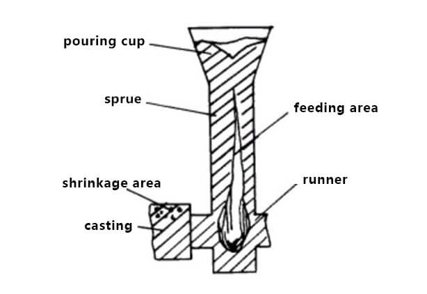
Part 3: Worked Example
Problem Statement
A steel casting has a feeding zone that is a rectangular plate with dimensions:
-
Length = 300 mm
-
Width = 200 mm
-
Thickness = 40 mm
Design a cylindrical riser with H/D = 1.5 using the modulus method.
Given:
-
Steel volumetric shrinkage ε = 5%
-
Modulus enlargement factor f = 1.2
Solution
Step 1: Calculate the casting modulus
For a plate, heat is lost primarily from the top and bottom surfaces (edges are negligible):
VC=300×200×40=2,400,000 mm3
AC=2×(300×200)=120,000 mm2
MC=VCAC=2,400,000120,000=20 mm=2.0 cm
Step 2: Determine the required riser modulus
MR=1.2×MC=1.2×20=24 mm=2.4 cm
Step 3: Calculate riser dimensions (H/D = 1.5)
For H/D = 1.5:
MR=0.1875D
D=MR0.1875=240.1875=128 mm
H=1.5×D=1.5×128=192 mm
Riser dimensions:
-
Diameter D = 128 mm (round up to 130 mm for practical sizing)
-
Height H = 192 mm (round up to 195 mm)
Step 4: Verify the riser modulus with rounded dimensions
With D = 130 mm, H = 195 mm:
MR=DH4H+2D=130×1954(195)+2(130)=25,350780+260=25,3501,040=24.4 mm
24.4 mm > 24.0 mm ✓ (requirement satisfied)
Step 5: Verify the feeding volume
Riser volume:
VR=πD2H4=π×1302×1954=2,587,000 mm3=2,587 cm3
Required feed metal:
Vfeed=ε×VC=0.05×2,400,000=120,000 mm3=120 cm3
The riser volume (2,587 cm³) far exceeds the required feed volume (120 cm³), so volume is sufficient.
Step 6: Calculate the riser neck modulus
MN=0.6×MR=0.6×24=14.4 mm
Check: M_C (20 mm) < M_N (14.4 mm)? No — 14.4 < 20!
This indicates a problem: if the neck modulus (14.4 mm) is less than the casting modulus (20 mm), the neck will solidify before the casting, blocking the feeding path.
Solution: Increase the neck size or use a different neck geometry so that M_N > M_C. For example:
MN=0.67×MR=0.67×24=16.1 mm
Still less than 20 mm. The neck needs to be enlarged so that:
MN>20 mm
This may require adjusting the neck dimensions or using a larger riser to increase M_R and consequently M_N.
Step 7: Select the riser sleeve
Based on D ≈ 130 mm and H ≈ 195 mm, select a standard riser sleeve from the manufacturer‘s catalog with:
-
Inside diameter ≥ 130 mm
-
Height ≥ 195 mm
-
Suitable for steel casting application
Part 4: Special Considerations
When Using Insulating or Exothermic Sleeves
Insulating and exothermic sleeves increase the effective modulus of the riser by reducing heat loss through the side walls and/or adding heat through exothermic reactions.
The apparent modulus of a sleeved riser is:
Mapparent=MEF×Mgeometric
where MEF (Modulus Extension Factor) is provided by the sleeve manufacturer. MEF values typically range from 0.50 to 0.90—the smaller the value, the more efficient the sleeve.
Practical implication: When using high-efficiency sleeves, you can use a smaller geometric riser while achieving the same feeding performance, significantly improving casting yield.
For Insulating Sleeves Specifically
When using insulating riser sleeves, the calculation follows a slightly different procedure:
-
Calculate the casting modulus M_C
-
Calculate the insulating riser modulus:
Mriser=(0.8∼0.9)⋅MC
-
Use the calculated M_riser value to look up the corresponding riser diameter, height, volume, and weight from manufacturer tables
The lower factor (0.8–0.9) reflects the fact that insulating sleeves slow heat loss, allowing a smaller modulus riser to achieve the same solidification time as a larger sand riser.
For Different Alloys
| Alloy | Key Considerations |
|---|---|
| Steel | High shrinkage (4–6%); use f = 1.2; modulus method is the primary design tool |
| Ductile iron | Graphitization expansion partially compensates for shrinkage; f can be lower (1.0–1.1) |
| Gray iron | Significant graphitization expansion; may not require risers for thin sections |
| Aluminum | Low shrinkage (~3–4%); feeding distance is shorter; multiple small risers may be preferred |
Part 5: Checklist for Riser Design Using the Modulus Method
-
Step 1: Identify all hot spots (feeding zones) in the casting
-
Step 2: Calculate the modulus (M_C = V/A) for each feeding zone
-
Step 3: Select the modulus enlargement factor (f) based on alloy
-
Step 4: Calculate required riser modulus (M_R = f × M_C)
-
Step 5: Choose riser shape (cylindrical is most common) and H/D ratio
-
Step 6: Solve for riser dimensions (D and H) using M_R formula
-
Step 7: Round dimensions up to practical/manufacturable sizes
-
Step 8: Recalculate M_R with rounded dimensions (verify M_R ≥ required)
-
Step 9: Calculate riser neck modulus (M_N ≈ 0.6–0.67 × M_R)
-
Step 10: Verify M_C < M_N < M_R (directional solidification)
-
Step 11: Verify feeding volume (V_R ≥ ε × V_C)
-
Step 12: Select standard riser sleeve from manufacturer catalog
-
Step 13: (Optional) Run casting simulation to validate design
Summary
The modulus method is a scientifically grounded, practical approach to riser design that has served foundry engineers for decades. By ensuring that the riser modulus exceeds the casting modulus (typically by 20% for steel), you guarantee directional solidification and proper feeding.
The key takeaways:
-
Modulus = V/A — the fundamental measure of solidification time
-
M_R = 1.2 × M_C — the riser must solidify after the casting
-
M_C < M_N < M_R — the neck must maintain the feeding path
-
Volume check — the riser must contain enough liquid metal
-
Sleeves improve efficiency — insulating and exothermic sleeves increase effective modulus, allowing smaller risers and higher yields
Modern casting simulation software can automate much of this calculation, but understanding the underlying modulus method remains essential for interpreting results and making sound engineering decisions.
Note: This guide presents industry-standard practices for riser design using the modulus method. Material properties, shrinkage values, and specific factors may vary depending on your alloy, molding process, and foundry conditions. Always validate designs through trials or simulation for your specific application.