

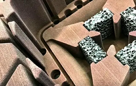
You’ve chosen silicon carbide (SiC) foam filters for your iron casting operation – good choice. SiC stands up to the high temperatures and aggressive dross of gray and ductile iron. But a great filter installed poorly will perform no better than a cheap one.
In iron casting, the stakes are higher. Pouring temperatures are 1350–1500°C. Metal head can be tall. The consequences of filter failure – bypass, cracking, or clogging – are misruns, scrap, and lost production.
Before You Start – Know Your Numbers
Before you touch a filter, have these specifications ready:
| Parameter | Why It Matters |
|---|---|
| Pouring weight (kg) | Determines required filter area |
| Choke area (cm²) | Smallest cross‑section in the gating system |
| Alloy type | Gray iron vs. ductile iron – different PPI recommendations |
| Filter PPI | 10–15 for ductile, 15–20 for gray iron (typical) |
| Filter material | Silicon carbide (not alumina for iron) |
Quick area rule: Filter area should be 3–5× the choke area. For ductile iron (more dross), use the higher multiplier.
Filter Selection – Material and PPI
Material: Silicon carbide (SiC). Do not use alumina for iron – it will soften or fail.
PPI selection guide:
| Alloy | Recommended PPI | Notes |
|---|---|---|
| Ductile iron (standard) | 10–15 PPI | Coarser pores handle sticky dross without clogging |
| Ductile iron (high quality) | 15–20 PPI | Finer filtration – increase filter area by 30–50% |
| Gray iron | 15–20 PPI | Gray iron has less slag; can use finer pores |
| Large / heavy castings (any iron) | 10 PPI | Prioritize flow over fine filtration |
Filter thickness: For iron casting, use filters at least 22 mm thick. Thicker filters (up to 50 mm) are available for very large castings.
Preheating – Critical for Iron
Unlike aluminum, where preheating is recommended but sometimes skipped, preheating for iron is mandatory. A room‑temperature SiC filter hit by 1400°C iron will experience extreme thermal shock. It can crack – sometimes invisibly – leading to bypass and unfiltered metal.
Preheating procedure:
| Step | Action |
|---|---|
| 1 | Place filters in a preheat oven or on a preheat table near the molding line. |
| 2 | Heat to 300–500°C (higher end for ductile iron, which pours hotter). |
| 3 | Hold at temperature for 30–60 minutes (longer for larger filters). |
| 4 | Remove filters just before mold closing – do not let them cool. |
If you don’t have a preheat oven: Some foundries use a gas torch to heat the filter seat area after placement, but this is less reliable. A dedicated oven is the best practice.
Storage tip: Keep filters in a dry area before preheating. Moisture + high heat = steam + potential gas defects.
Creating the Filter Seat
The filter seat is the recess in the sand mold where the filter sits. It must be precisely formed to prevent metal bypass and provide support.
Seat requirements for iron casting:
| Feature | Requirement | Why |
|---|---|---|
| Flatness | ≤0.5 mm deviation | Prevents rocking and stress cracks |
| Depth | Equal to filter thickness | Filter should be flush with runner floor |
| Clearance | 0.5–1.0 mm gap on each side | Easy placement; seal gap with refractory paste |
| Support | Full bottom support | No overhangs; metal pressure won’t break unsupported edges |
| Rounded corners | Radii at bottom edges | Reduces sand erosion and stress concentration |
How to form the seat:
-
Pattern‑mounted: Use a removable filter print in the pattern. This creates the seat automatically during molding.
-
Hand‑cut: After ramming the mold, use a flat tool to carve the recess. Check depth and flatness with a straightedge.
For large castings (e.g., >500 kg): Consider using a ceramic filter box – a preformed refractory housing that holds the filter. This provides better support and sealing than a sand seat.
Placing the Filter – Position and Orientation
Optimal position: In the runner, as close to the casting cavity as possible. This minimizes reoxidation after filtration.
Do NOT place directly under the sprue. The high‑velocity metal stream from the sprue can:
-
Erode the filter face
-
Cause premature clogging
-
Push the filter out of position
Correct placement:
Pouring cup → Sprue → Sprue well → Runner → [FILTER] → Gate → Casting cavity
Orientation: Place the filter horizontally, with the flat face perpendicular to the metal flow. Some foundries use a vertical orientation in tall runners – both work if properly sealed.
For multiple filters: Use several filters in parallel (not in series) to increase total filter area. Each filter must be in its own seat, with metal flow distributed evenly.
Sealing – No Bypass Allowed
Unfiltered metal bypassing the filter is the #1 reason filters “don’t work.” If metal finds a path around the edge, your expensive SiC filter is useless.
Sealing methods for iron casting:
| Method | Application | Steps |
|---|---|---|
| Ceramic fiber gasket | Best for iron (high temperature) | Place gasket in seat, then filter on top; gasket compresses to seal |
| Refractory paste | Good for moderate temperatures | Apply 2–3 mm layer around seat edge; press filter into paste |
| Sand seal | Not recommended for iron | Unreliable; metal can wash away sand |
Step‑by‑step sealing with gasket:
-
Cut a ceramic fiber gasket to match the filter shape, slightly larger than the seat.
-
Place the gasket in the filter seat.
-
Press the filter onto the gasket – the gasket should protrude slightly.
-
When the mold closes, the cope presses down, compressing the gasket and creating a tight seal.
After placement, inspect: No gaps should be visible between filter and sand. If you see a gap, add a dab of refractory paste.
Supporting the Filter – Preventing Breakage
Iron casting involves tall metal heads (sometimes >500 mm). The weight of the metal column can push down on the filter. Without proper support, the filter can crack or tilt.
Support requirements:
-
Full bottom support – the filter should not overhang an empty space.
-
Seat depth – filter sits below runner floor level (recessed), not proud.
-
For large castings – use a metal or ceramic support grid under the filter.
What to avoid:
-
Filter protruding above runner floor – metal impacts the edge, causing erosion.
-
Filter seat with a central void – unsupported area cracks under pressure.
Pouring – What to Watch For
During pouring, observe these indicators:
-
Sprue should stay full – If the sprue level drops, the filter may be clogging or too small.
-
Pouring time – Should match your calculated time. Longer time indicates flow restriction.
-
Metal backflow – If metal backs up into the sprue, the filter may be blocked.
If the filter clogs during the pour: Stop. Clean the filter seat and try a coarser PPI or larger filter area for the next run.

After Shakeout – Inspect the Used Filter
Learn from every pour. After shakeout, retrieve the used filter and examine it:
| What You See | What It Means |
|---|---|
| Heavy, dark, clogged with dross | Filter worked – captured many inclusions. |
| Clean and light | Either melt was very clean, or metal bypassed (check sealing). |
| Cracked | Thermal shock – preheat more next time. |
| Broken edges | Mechanical stress – check support and handling. |
| Metal on sides | Bypass – improve sealing. |
Track this information. It will guide you to better PPI, area, and installation practices.
Common Mistakes in Iron Casting Filter Installation
| Mistake | Consequence | Prevention |
|---|---|---|
| No preheat | Thermal shock cracks | Preheat to 300–500°C |
| No seal (gasket or paste) | Metal bypass – zero filtration | Always use gasket |
| Filter too small for casting | Flow restriction, misrun | Calculate required area (3–5× choke) |
| Wrong PPI (20 on ductile) | Clogging, premature failure | Use 10–15 PPI for ductile iron |
| Placing under sprue | Erosion, clogging | Place in runner, away from sprue impact |
| Uneven support | Cracking | Ensure full flat seat |
| Not inspecting used filters | Repeat same mistakes | Inspect every shift |
Quick Reference Card
| Step | Action |
|---|---|
| 1 | Select SiC filter, correct PPI and size |
| 2 | Preheat filter to 300–500°C for 30–60 min |
| 3 | Form flat, fully supported filter seat |
| 4 | Place ceramic fiber gasket in seat |
| 5 | Set filter on gasket – flush with runner floor |
| 6 | Seal edges – no gaps |
| 7 | Close mold carefully |
| 8 | Pour, keeping sprue full |
| 9 | Inspect used filter after shakeout |
| 10 | Adjust PPI or area based on results |
Conclusion
Installing SiC foam filters in iron casting gating systems requires attention to detail – but the steps are straightforward:
-
Preheat (300–500°C) – mandatory for iron.
-
Seal with ceramic fiber gasket – no bypass.
-
Support the filter fully – no overhangs.
-
Size correctly – 3–5× choke area, coarser PPI for ductile iron.
-
Inspect used filters – learn and improve.
When done right, SiC filters will remove dross and sand inclusions, reduce scrap, and improve machinability. When done wrong, they’ll crack, bypass, or clog – and you’ll blame the filter instead of the installation.
Need help sizing a filter for a specific iron casting? Send us your gating layout and casting weight – we’ll recommend the right SiC filter and installation method.
Contact SF-Foundry Technical Support:
Email: info@sf-foundry.com
Phone / WhatsApp: +86 18636913699
Website: www.sf-foundry.com
For aluminum casting filter installation, see our separate guide: How to Install Ceramic Foam Filters: Placement and Preheating Tips.