

Ceramic foam filters are engineered to deliver exceptional molten metal cleanliness, but even the highest quality filter can fail to perform if installed incorrectly. Improper installation leads to filter breakage, restricted metal flow, and compromised casting quality—directly impacting your foundry’s productivity and bottom line.
This guide provides practical, step-by-step instructions for proper ceramic foam filter installation, covering everything from preheating to placement. Based on years of industry experience and technical best practices, these recommendations will help you get the full benefit from your filtration investment.
Why Proper Installation Matters
The Consequences of Poor Installation
| Problem | Likely Cause | Result |
|---|---|---|
| Filter cracks during pouring | Thermal shock from inadequate preheating | Fragments enter casting, causing inclusions |
| Metal bypasses filter | Poor sealing around edges | No filtration occurs |
| Filter floats or shifts | Improper fixation | Unfiltered metal enters mold |
| Slow mold filling | Filter area too small or wrong placement | Cold shuts, misruns |
| Premature clogging | Poor flow distribution | Reduced effective filtration area |
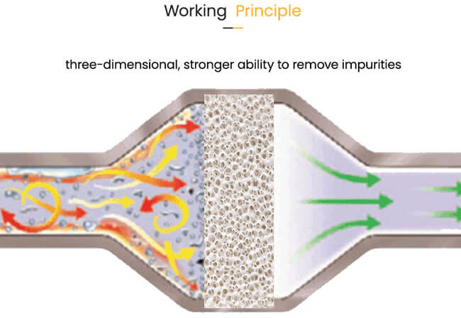
The Filter’s Dual Role
A properly installed ceramic foam filter does more than just trap inclusions. Research confirms that filters transform turbulent flow into laminar flow, significantly reducing re-oxidation within the mold and minimizing sand erosion risk. But this only happens when the filter is correctly positioned and sealed.
Preheating—The Most Critical Step
Why Preheating Is Essential
Placing a cold filter into molten metal creates severe thermal shock. The dramatic temperature difference between a room-temperature filter and molten metal (e.g., 720°C for aluminum, 1450°C for iron) causes thermal stress that can crack or shatter the ceramic structure.
Proper preheating:
-
Prevents thermal shock cracking
-
Removes moisture that could cause gas defects
-
Opens filter pores (avoids occlusion from thermal expansion)
-
Ensures the filter reaches near-molten temperature for smooth flow initiation
Recommended Preheating Parameters
Based on SF-FOUNDRY‘s extensive testing and field experience, follow these guidelines:
| Parameter | Recommendation |
|---|---|
| Preheating temperature | 600-800°C (adjusted according to filter size and alloy) |
| Preheating time | ≥30 minutes (large filters may need 1 hour) |
| Heating rate | ≤10°C per minute (avoid rapid heating that causes thermal stress) |
| Preheating method | Dedicated preheating furnace is safer than direct flame heating |
Preheating Best Practices
-
Use a controlled oven: Direct flame creates hot spots and uneven heating.
-
Soak time matters: Ensure the filter core reaches temperature—30-45 minutes minimum for standard 50mm thick filters.
-
Preheat the filter box too: The filter seat or box should also be preheated to match filter temperature.
-
Temperature verification: If available, use a pyrometer to confirm temperature.
Special Note for Aluminum Casting
For aluminum applications, preheating to at least 260°C is essential, though higher temperatures (closer to melt temperature) are better. Proper preheating allows the expanding sealing gasket to seal effectively and prevents molten aluminum from solidifying in the pores upon first contact.
Choosing the Right Installation Location
General Principle
The filter should be placed as close to the casting cavity as possible to maximize filtration efficiency and flow conditioning, and to minimize the probability of secondary oxidation after filtration.
Common Installation Positions
| Position | Suitability | Considerations |
|---|---|---|
| Under the sprue cup | Good for simple castings | Easy to install, but may not protect entire runner system |
| In the runner (horizontal) | Most common, recommended | Allows even flow distribution; best balance of protection and practicality |
| At runner and ingate junction | Good for complex castings | Catches inclusions generated in runner |
| Bottom of sprue | Not recommended | Turbulent flow from sprue bottom affects filter performance |
| Vertically in runner | Excellent for large castings | Provides good flow control, saves space |
Special Cases
-
If using in-mold nodularization or inoculation: Place the filter after the reaction chamber, as close to the runner as possible.
-
For aluminum lower casting method: Position filter horizontally so metal rises evenly, reducing turbulence and ensuring even filter startup.
Distance Recommendations
For optimal performance, position the filter 50-100mm from the pouring cup.
Filter Seat Design and Support
Proper Support Prevents Breakage
The filter must be fully supported across its entire bottom surface. Uneven support creates stress points that can cause cracking under metal pressure.
Filter Seat Requirements
| Parameter | Recommendation |
|---|---|
| Support surface flatness | Error ≤ 0.5mm |
| Seat design | Stepped filter seat preferred (reduces bottom stress) |
| Rounded corners | Use rounded corners on support surface to prevent sand washing |
| Support width (outflow side) | ≥5mm for standard filters; 10-12mm for filters >100×100mm |
| Overlap (inflow side) | 3-5mm overlap should be left |
| Gap allowance | 1-1.5mm gaps with sand-collecting grooves prevent sand from falling |
| Height relative to parting line | Filter upper surface should be 0.5-1mm lower than parting surface to avoid crushing when closing mold |
For High-Temperature Applications
When using cast iron fixtures to support filters, ensure they can withstand 1300°C+ temperatures without deforming.
Sealing—Preventing Bypass Flow
Why Sealing Matters
If molten metal can flow around the filter instead of through it, filtration is completely ineffective. Turbulent flow through gaps can also erode the filter box refractory, introducing new inclusions.
Sealing Methods
| Method | Application |
|---|---|
| Ceramic fiber gasket | Press sealing gasket around filter edges by hand |
| Refractory paste/mud | Apply around edges to seal gaps ≤1mm |
| Expanding seal | Some materials expand during preheating to create positive seal |
Sealing Best Practices
-
Gap tolerance: Maximum recommended gap is 1-2mm per side.
-
Complete perimeter: Seal all edges—not just the sides that look problematic.
-
Verify before pouring: After installation, visually confirm the seal is continuous.
At SF-FOUNDRY, we recommend using ceramic fiber sealing gaskets designed specifically for filter applications. When properly preheated, these gaskets expand to create a positive seal that prevents metal bypass.
Installation Step-by-Step
Step 1: Inspection
Before installation, inspect the filter:
-
Check for visible cracks (use strong light to see through)
-
Verify dimensions match the filter seat
-
Ensure filter is clean and free of debris
Step 2: Preheating
-
Place filter in preheating furnace
-
Heat to 600-800°C at ≤10°C/minute
-
Hold for minimum 30 minutes (longer for larger filters)
-
Preheat filter seat simultaneously if possible
Step 3: Placement
-
Complete installation within 15 minutes after preheating
-
Gently lower filter straight down into seat—do not drop or tilt
-
Ensure filter sits perfectly horizontal and fully supported
-
Press sealing gasket around all edges
Step 4: Final Check
-
Verify filter is level and secure
-
Confirm no gaps remain around perimeter
-
Check that filter will not shift during mold closing or pouring
Step 5: Pouring
-
Initial pouring: Maintain 50% normal flow for 2-3 seconds to allow smooth startup
-
Monitor metal height in sprue
-
Normal starting height: 100-150mm above filter
-
During flow, height may drop to 75-100mm then slowly increase
Pouring Parameters and Monitoring
Recommended Pouring Speeds by Alloy
Based on SF-FOUNDRY‘s technical database:
| Metal Type | Recommended Pouring Speed | Maximum Impact Height |
|---|---|---|
| Aluminum alloy | 0.5-1.2 kg/s | ≤150mm |
| Cast iron | 1.5-3.0 kg/s | ≤100mm |
| Copper alloy | 0.8-1.8 kg/s | ≤120mm |
Monitoring During Pouring
-
Observe metal height: Maintain steady flow; avoid sudden surges
-
Watch for signs of clogging: If metal height rises unusually, flow may be restricted
-
Avoid vibration: Do not hit or shake the filter during filtration
-
Control launder flow: Never let flow rate become too high or too low
After Pouring
-
Take out used filter promptly after casting
-
Clean filter box or seat before next use
Filter Area Calculation
Why Area Matters
The filter must be large enough to handle the required flow rate without excessive pressure drop. The general principle: filter working area should be 4-6 times the choke cross-sectional area of the gating system.
Minimum Recommended Filter Area
| Application | Minimum Filter Area vs. Choke Area |
|---|---|
| General castings | ≥4× choke area |
| Aluminum alloys | 4-6× choke area |
| Iron castings | 4× choke area |
| High-flow applications | May require larger area |
Flow Rate Consideration
Filter flow resistance increases as inclusions accumulate. For large castings, consider multiple filters or larger filter sizes to maintain adequate flow throughout pouring.
Common Installation Mistakes and How to Avoid Them
Mistake 1: Inadequate or Uneven Preheating
The Error: Placing a cold or only partially warmed filter into the mold.
Consequences: Thermal shock cracks the filter; gas bubbles from moisture enter the metal.
Solution: Follow the preheating protocol strictly—600-800°C for ≥30 minutes.
Mistake 2: Incorrect Fit and Poor Sealing
The Error: Filter too small (gaps around edges) or too large (forced into place).
Consequences: Bypass flow renders filtration useless; erosion creates new inclusions.
Solution: Verify dimensions before installation; use ceramic sealant around all edges.
Mistake 3: Improper Handling and Placement
The Error: Rough handling, dropping, or placing filter at an angle.
Consequences: Mechanical damage creates failure points; uneven flow leads to premature clogging.
Solution: Handle filters as precision components; use gentle, level placement.
Mistake 4: Ignoring Support Structure
The Error: Placing filter on uneven surface or insufficient support width.
Consequences: Stress cracking under metal pressure; filter may shift during pouring.
Solution: Design proper filter seat with adequate support and flatness.
Mistake 5: Wrong PPI for Available Head Pressure
The Error: Using fine PPI filter in system with insufficient metal head.
Consequences: Slow fill, incomplete mold filling, or misruns.
Solution: Match PPI to your system’s capabilities; ensure adequate head pressure.
Mistake 6: Placing Filter Too Far from Casting
The Error: Filter located too early in gating system, allowing reoxidation after filtration.
Consequences: Secondary inclusions form after filter, defeating purpose.
Solution: Place filter as close to casting cavity as practical.
Frequently Asked Questions
Q1: Can I reuse ceramic foam filters?
A: Generally, no. Ceramic foam filters are brittle and easily damaged. They are typically used only once. If reuse is attempted, melt insulation measures must be adopted, but it’s generally not allowed to use more than seven times. A new filter must be replaced within 48 hours.
Q2: What happens if I don’t preheat the filter?
A: The filter will likely crack from thermal shock. Even if it doesn’t crack visibly, micro-cracks may form that weaken the structure. Moisture in the cold filter can also vaporize and cause gas defects.
Q3: How do I know if my filter area is sufficient?
A: Monitor metal height during pouring. If height increases significantly above normal startup levels, the filter may be too small or clogging prematurely. The general rule is filter area ≥4× choke area.
Q4: Can I use a torch to preheat the filter?
A: Not recommended. Direct flame creates hot spots and uneven heating, which can cause thermal stress cracks. A dedicated preheating furnace is safer and more effective.
Q5: What is the ideal distance from pouring cup to filter?
A: 50-100mm is recommended for most applications.
Q6: How do I prevent filter floating during pouring?
A: Proper sealing and support are key. Use a stepped filter seat, press sealing gasket firmly around edges, and ensure the filter is fully supported on the bottom. Preheating helps sealing materials expand and grip the filter.
Q7: My filter cracked during pouring. What went wrong?
A: Most common causes: inadequate preheating (thermal shock), uneven support (stress concentration), or mechanical damage during installation. Review your preheating protocol and check filter seat flatness.
Conclusion
Proper installation of ceramic foam filters is essential for achieving clean castings and maximizing the return on your filtration investment. The key principles are simple but critical:
-
Preheat properly — 600-800°C for ≥30 minutes, controlled heating
-
Place correctly — Close to casting, level, fully supported
-
Seal completely — No gaps around edges
-
Size appropriately — Filter area ≥4× choke area
-
Pour carefully — Control speed and impact height
Following these guidelines transforms your ceramic foam filter from a simple consumable into a reliable process control tool that consistently delivers cleaner metal, better castings, and higher foundry efficiency.
Need Installation Support?
At SF-FOUNDRY, we don’t just manufacture high-quality ceramic foam filters—we help you use them effectively. Our silicon carbide ceramic foam filters undergo special thermal shock treatment that, with correct installation, can increase service life by up to 40%.
We offer:
-
Installation guidance videos
-
On-site technical support
-
Engineering consultation for challenging applications
-
Custom filter sizing recommendations
Contact our technical team for assistance:
SF-FOUNDRY
Website: https://sf-foundry.com/
Email: info@sf-foundry.com
WhatsApp: +8618636913699