

Major challenges foundries face in recent times include frequent product rejections mainly caused by inconsistency in quality, excessive defects, and failure of cast iron in high-stress applications. In a survey of over 200 foundries, more than 7.4% of the rejection rate was due to integrity defects alone.
Your casting operation should be optimized with a proper gating system in order to maintain a consistent pouring and avoid contamination, which will increase the purity of your cast iron.
In this article, you’ll discover how SIC foam filters can help you revamp cast iron’s purity. You will also learn how to select a filter that is tailored for your casting operation.
What Are SiC Foam Filters?
SiC foam filters are silicon-based ceramic materials designed with a three-dimensional network of interconnected pores. They are made from a precise blend of silica sand, carbon, binders, and additives, processed through sintering techniques to create highly porous and thermally stable structures.
They are used in the purification and filtration of cast iron and copper-based alloys to remove unwanted inclusions, oxides, and other impurities that can lead to defects, ultimately reducing the product rejection rate.
The challenge in reducing the climbing defect rate is that they don’t form on their own. They are a result of the reaction the molten metal undergoes during the casting stage. The silicon carbide foam acts as a medium that minimizes the defect rate, by manipulating the flow of the molten metal through the porous structure.
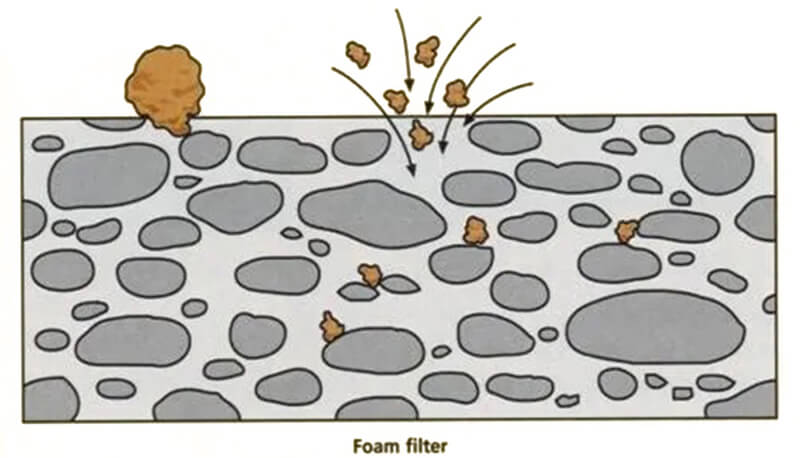
The filters are designed to remove impurities that get trapped in various ways. This occurs through cake formation, mechanical screening, and the adsorption mechanism, all enforced to handle both physically carried and chemically formed inclusions.
Importance Of SiC Foam Filters
The importance of purified, inclusion-free melt entering the casting mold shouldn’t be overstated. It’s more than necessary. Customers aren’t buying alloy components, nor are they purchasing the chemical elements present in the cast iron itself. They are looking for materials that can last, that are durable in tough conditions, and that can resist heat, damping, and more. They care about how the material performs (its mechanical properties).
The automotive industry, which largely relies on iron and alloys, is leaning toward reducing emissions and fuel consumption. There’s a growing focus on using lighter-weight, more resistant materials. The industry is adapting to high-strength steel. To maintain structural integrity, it’s crucial to minimize defects like nodule counts and nodularization failures, which frequently cause poor inoculant performance.
It’s clear that you can no longer retreat (scraping and removing defects) damaged products in order to expand further. Those defects will keep recurring. Instead, you need to start recognizing and offering solutions to improve structural integrity by addressing sources like non-metallic inclusions, gas entrapment, and uneven cooling in molds.
The integration of SiC ceramic foam filters allows foundries to minimize the risk of weakness in their material and balance their mechanical properties.
How SiC Foam Filters Improve Purity?
The purity of the metal is not entirely graded by inclusion-free casting. It is assessed based on its chemical composition, metallurgical structure, and the minimality of impurity levels. Although these parameters don’t speak for themselves, they will largely reflect their ability to withstand tough environments and determine their machinability.
There are hundreds of parameters a foundryman has to check. And especially in the casting process, removing trapped particles is one of them. Apart from this, optimizing SiC ceramic foam filters for your iron casting operations ensures:
- The impurities get trapped, including both physically carried and oxidized particles.
- No turbulence within the mold, which helps avoid gas entrapment.
- The temperature remains even across the melt, ensuring uniform solidification.
- Contamination does not occur.
- The surface finish of the casting remains uniform.
And these tortuous channels are built in a way that allows the molten liquid to interact with the surface of the filter as many times as possible. This interaction helps adhere tiny particles to the surface of the filter. The frequent directional changes also help guide the flow on a linear path.
Let’s find out how these filters improve casting purity in detail…
Removing Inclusions
Inclusions in cast iron are foreign materials, such as slag, oxides, sand, and non-metallic impurities. The presence of these inclusions, particularly sand, can negatively affect the integrity of the casting process and significantly contribute to defects.
In sand casting, several incidents are closely linked to casting sand getting trapped in the mold. These can occur due to the collapse of the sand wall or core, inadequate ramming, or, in some cases, the sand losing its strength. When this happens, the sand tends to wash away into the mold. Among the various types of inclusions physically carried through the mold, sand inclusions alone account for about 30–40% of the rejection rate in molded casts.
Similarly, non-metallic inclusions are not generated on their own. They are formed through specific reactions, as given below.
- Exogenous inclusions: These are external inputs to the melt (such as mold sand, oxides, and slag entrapment). They commonly affect the surface finish and machinability of the cast.
- Endogenous inclusions: These result from internal reactions in the melt (such as deoxidation and precipitation).
Inclusions can be referred to as stress raisers, whether they are large or small in volume fraction. Their presence in the molten iron, shapes and controls the behavior of the material entirely. As long as they remain trapped within the cast, they become more vulnerable to failures like cracks or fractures when exposed to external forces, where they tend to experience severe stress.
Dross is a type of inclusion that occurs in ductile iron, causing the material to lose its ductility and strength in most cases. It results from the metal being exposed to air or slag. Dross primarily consists of oxides, which are often non-metallic; they do not bond well with the metal matrix. When these inclusions get trapped inside the mold, they form links with one another, spreading throughout the casting. This is one of the reasons why metals may not remain stable under heavy pressure. Although welding seems like a viable solution, the non-metallic nature of the inclusions impairs the fusion process, resulting in weak joints even after welding.
Here the ceramic foam filter decelerates the flow of molten metal. By reducing its velocity, it increases the contact time between the filter surface and the molten liquid. Forcing the liquid to change direction multiple times as it passes through the labyrinthine path. The direct sieving mechanism captures inclusions with larger pore sizes, while smaller inclusions are attracted to the rough surface of the filter through wetting and adhesion.
A quick tip: To capture sub-micron-sized inclusions, use finer porosity filters or a multi-stage filtration system. Combining various grades of filters will remove a wide range of inclusions.
Minimizing Oxidation Defects
These defects appear as cracks or discolored surfaces. They are typically caused by a poor surface finish, weak bonding between layers, or small voids within the cast material. They usually occur when oxidized particles (e.g., metal oxides or slag) are carried through the metal. The entrapment of these particles weakens the material’s binding properties.
Oxidation is an ongoing, continuous process that cannot be stopped. It only ceases when the entire cast solidifies. Iron tends to be rich in chemical compositions, which is one of the reasons it has a higher oxygen content—around 2.4 PPM. With the addition of free oxygen in iron, this becomes even more extreme.
The aggressive nature of oxygen to combine and form oxide molecules cannot be halted. However, gating the flow with porous filters prevents the contaminated byproducts from reaching the final yield.
Preventing Gas Contamination
If you’re counting the reasons for casting materials losing their mechanical properties, gas porosity will be at the top. During the casting process, gases from the atmosphere, such as nitrogen (N₂) and hydrogen (H₂), can dissolve in the molten metal. The reaction between liquid iron and these gases forms compounds like nitrides and hydrides.
Additionally, during the smelting process, the melt can generate slags that consist of various oxides, such as iron oxide (FeO), calcium oxide (CaO), and silicon dioxide (SiO₂).
C(solid) + O(from slag) → CO(gas)
The CO gas formed during this reaction can become trapped within the molten alloy. As the liquid solidifies, these gas bubbles may remain trapped, leading to gas porosity—creating voids or pores within the material.
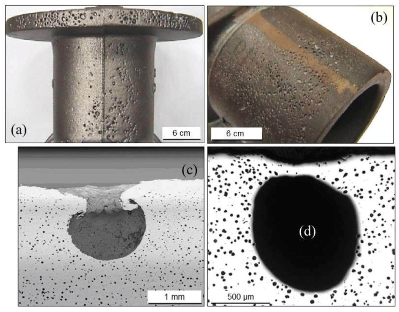
Gas porosities lead to various types of casting defects, and pinholes are one of them. These can appear on the cast skin, typically on the upper surface of the casting. They range from small groups of fine holes to a single large spherical pore. Pinholes can significantly affect the strength of cast iron, often leading to cracking or failure under stress.
The ceramic foam filter works on the principles of surface tension and adhesion. As molten metal passes through its porous medium, gas bubbles (mainly nitrogen and hydrogen) attach to the surface of the filter, becoming physically trapped. This process prevents the melt from becoming overloaded with dissolved gases and supersaturated.
Improving Metal Homogeneity
No component should have a weak spot, and no area should be stronger than others within the same metal. Defects like porosity and localized corrosion are major indicators of inhomogeneity within the cast. They result from the absence of certain mechanical and chemical compositions.
A typical mold contains a mixture of carbon, silicon, and alloying components. These elements should be evenly distributed across the cast. When they’re missing, weak spots form.
The removal of impurities and the reduction of turbulence help minimize hot spots and irregular cooling rates in the liquid. As a result, the structure becomes stable throughout, and stress can’t easily cause failure, even under tough treatments.
Factors That Decide The SiC Foam Filter Efficiency
Foam filters are one of the refractory components that facilitate quality casting. Apart from that, the foundry relies on various factors that decide the efficiency of the mold:
- Properties of the liquid iron (How hot the melt is, whether it’s thin and less viscous, or thick, and its composition)
- The filtration process (the filtration rate, any preheating done beforehand, or how the entire casting system is designed)
- Characteristics of inclusions (What their size and structure are, how many of them are present)
- The foam filter itself (The shape and size of the filter, how porous it is, and the materials composing the filter)
Choosing a poor filtration system tends to lead to quick erosion. It might also create infiltration issues that should be addressed. When looking for a SiC ceramic foam filter, particularly for cast iron, keep an eye on these factors to ensure your foam filters meet the mark.
Pore Size and Distribution
The foam filter has a number of pores, linearly given per inch, with variations in their diameter throughout the structure. Every filter has its own unique sizes and distribution of pores. You can’t force-fit fine-sized pores into a large-shaped inclusion separation.
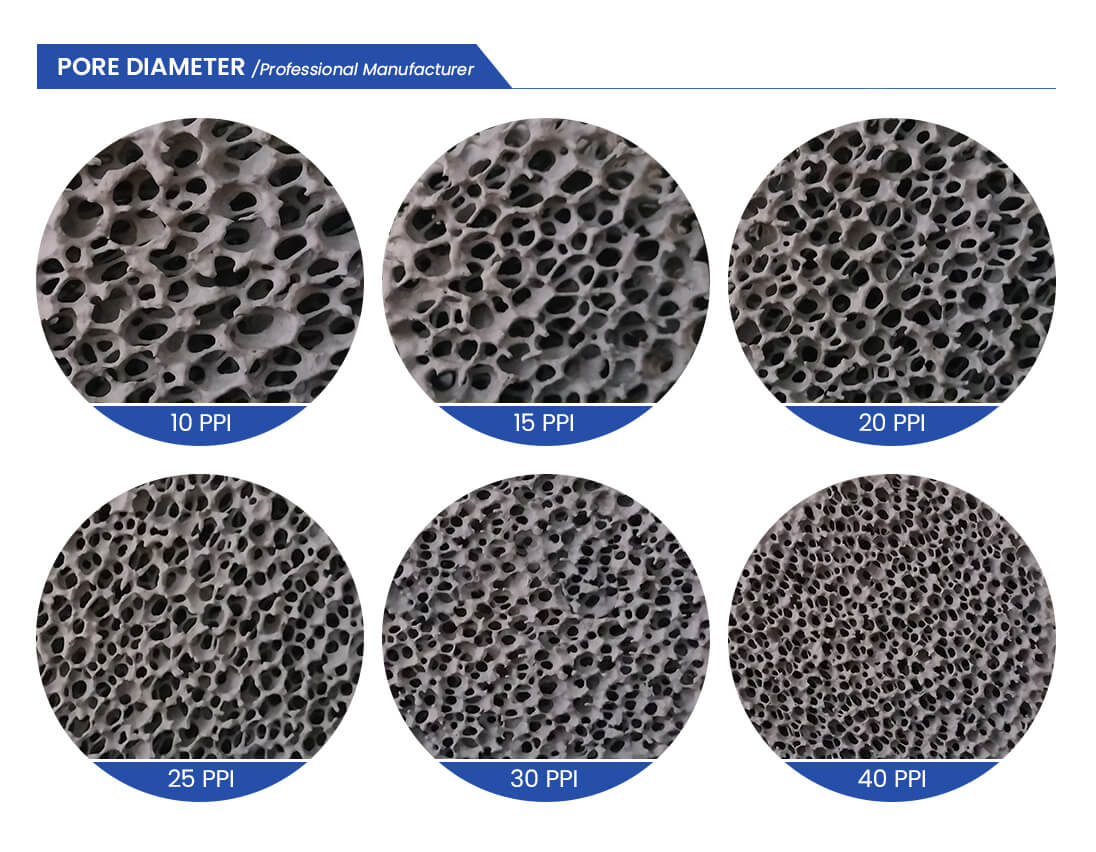
Ceramic foam filters are classified based on their PPI (Pores Per Inch) value, which refers to the number of pores within a linear inch of the filter material. A higher PPI means smaller pores with a denser and more closely packed distribution. On the other hand, a lower PPI indicates larger, more open pores with a coarser distribution.
The PPI value directly determines the filter’s purpose. For example, fine pores (30 PPI and above) provide better cleanliness, making them ideal for cast iron components that require a high-quality surface finish, such as engine blocks, pump housings, or intricate machinery parts. In contrast, coarser pores (10 PPI to 20 PPI), with their higher flow rate, are better suited for large-scale cast iron applications like manhole covers, counterweights, or structural components, where rapid flow and volume are the priority.
The uniform distribution of pores ensures that no empty space is created on the surface of the casting mold. This is one of the reasons why iron parts often develop weak spots or experience turbulence during casting. Variations in pore size distribution can allow small particles to slip through the voids in large castings, or they can lead to damaging mechanical properties of the final product that contribute to cracking. Additionally, a congested path can restrict flow, increasing the risk of premature solidification.
Ask yourself these questions before deciding on the porosity of the ceramic foam filter:
- Is the molten metal more fluid or thicker and harder to flow?
- How much pressure drop can the system tolerate?
- Are inclusions concentrated in specific areas of the melt or spread out?
- What is the desired flow rate?
One of the added advantages of these ceramic foam filters is the range of their pores. They are designed to offer better resistance against thermal shock and adapt quickly to surging temperatures. Whether fine, medium, or coarse, all types feature high open porosity (75–90 vol.%), which improves thermal mass (overall density) and minimizes the amount of heat the filter absorbs. This also eliminates the need for preheating the filter before use, saving both time and energy for foundries.
Thermal Resistance
Silicon carbide, the base material, is highly conductive. It has a thermal conductivity of 120 W/m·K. The raw material can distribute heat evenly, without localized radiation. However, the porous structure of the ceramic foam—composed of 94–96% air—greatly reduces the thermal conductivity compared to solid SiC.
The presence of air pockets acts as a thermal insulator. As the porosity of the ceramic foams increases, the materials become less thermally conductive, but permeability also increases, which can be beneficial for fluid flow in casting. To avoid thermal stress in your casting, maintain a balance between porosity and material composition.
Note: High porosity filters can improve thermal resistance under high temperatures (e.g., cast iron at 1500°C), but they can also reduce the flow rate. So, make sure the filter’s permeability aligns with the metal flow needs.
Another critical aspect of silicon carbide ceramic foam filters is their thermal shock resistance. The importance of a low CTC (coefficient of thermal expansion) is to avoid thermal stress. Foam filters that aren’t properly preheated during treatment tend to experience a sudden shock when in contact with high temperatures (up to 1500°C). Silicon carbide has a low CTC (around 4 × 10⁻⁶/°C), making it less likely to crack under extreme conditions.
Flow Rate and Pressure Drop
Consistency in liquid flow is imperative. The foam filter’s function is to smooth the flow without causing any restriction. It should not increase the pouring time either.
Pressure drop and flow rate are inversely proportional to each other:
- Higher pressure drop results in a lower flow rate (restricting metal movement).
- Lower pressure drop allows a higher flow rate (ensuring smooth and timely filling).
As a foundryman, you should aim to minimize the pressure drop to allow for easier liquid flow. This can be influenced by several factors, such as the porosity and thickness of the filter, the viscosity of the metal, inclusion load, and pressure head, among others.
Foundries typically expect high flow rates because they can quickly move liquid through the filter. However, this comes at a cost. A higher flow rate requires the filter to have larger pores or lower pore density. While this reduces resistance to flow, it also means a lesser pressure drop and a decreased ability of the filter to capture smaller inclusions.
As we’ve already discussed, whether it’s a small group of inclusions or a single large one, they can cause significant damage to the casting. Over time, these small particles will accumulate and may lead to premature filter blockage. The higher the efficiency, the easier it is for them to clog, so keep that in mind.
To eliminate undue pressure drop or clogging, make sure the filter is larger than the choke area or frontal area (the smaller cross-sectional area through which the mold flows) of the gating system. This will reduce the risk of blockage and help produce a smoother flow of liquid.
The filter size relative to the choke varies depending on the type of casting. For example, for thin-walled castings, where the flow needs to be controlled with high precision, the ratio should be 8:1. A larger filter area ensures there’s no blockage or restriction in the flow. For standard castings, where the flow rate doesn’t need to be as tight, a slightly smaller ratio of 4:1 may suffice.
As long as there is no hindrance in its motion, it will stay clear of turbulence and air to get trapped in its way. Additionally, smooth flow helps prevent inclusions from settling, which could cause defects in the casting.
If you need customization support?
Will you be provided with it?
Unfortunately, you can’t expect it from the filter itself. They are designed and intended for specific applications, as per the parameters mentioned above.
To choose the ideal filters, you need to ensure that all these factors match your filtering metal and the filtration medium. While the research and analysis will take away your time. But you don’t have to do that at all. SEFU is an industry leader, with over a decade of experience in producing ISO-certified SiC ceramic foam filters.
Our experts will guide you through the best solutions for your casting needs, providing you with technical support. You’ll receive assistance with tailored product production, material composition changes, pore structure adjustments, and density and thickness modifications to suit your application.
Optimize Your Foundry With SiC Foam Filters
Product failures and the recurring challenge of scrap removal are byproducts of a complex casting process. While these outcomes can’t be eliminated, what can be controlled is their source: the point where the defects begin to accumulate. In most cases, this is the gating system. That’s where defects begin, with the accumulation of inclusions and gas bubbles, and inconsistencies in flow occur, leading to turbulence or stagnation zones.
If you’re looking for a trusted and reputable SiC foam filter manufacturer that offers a variety of products in different dimensions, SEFU Ceramic is the one, optimized with custom-made and customizable solutions for your needs. Additionally, we offer free samples of our SiC foam filters.
If you are interested in receiving technical guidance, contact our experts here to save time.
FAQs About Silicon Carbide Foam Filters
Q1. Will the filter material react with my alloy or introduce contamination?
Silicon carbide-based filters don’t react with ferrous alloys like ductile iron and gray iron. However, their compatibility can vary with nonferrous alloys, such as aluminum and copper.
Q2. Does the filter material infiltrate the molten metal?
No, the filter materials are chemically inert and non-reactive under high temperatures. They neither dissolve nor contaminate the pouring metal. Instead, they facilitate infiltration by allowing a smoother and more controlled flow through the porous structure.
Q3. How does the filter handle continuous flow during high pressure?
The filter contains multiple flow paths within its porous network. When the primary channel encounters increased pressure or partial blockage, the molten metal is redirected through alternate pathways, ensuring a smooth flow and mitigating disruptions even under high pressure.
Q4. How to choose the right pore size for ceramic foam filters?
Match the pore size to the gating system’s choke area and flow demands for optimal performance.
References:
- Zhang, Lifeng & Thomas, Brian. (2003). Inclusions in continuous casting of steel. XXIV National Steelmaking Symposium. 1.
- Mrs. Deshmukh, V. S. and Dr. Sarda, S. S. The Critical Casting Defect in Cast Iron: Sand Inclusion – A Review. International Journal of Mechanical Engineering and Technology, 6(9), 2015, pp. 30-42.
- ‘Inclusions in Cast Iron’, Foundry Practice, no. 212 (1986), pp.11-15 (p. 12).
- Claudia Voigt, Eric Werzner, Robert Fritzsch, Jana Hubálková, Massoud Hassanabadi, Ragnhild E. Aune, Murilo D.M. Innocentini, Christos G. Aneziris, Influence of filter surface roughness on the pressure drop of ceramic foam filters, Open Ceramics, Volume 15, 2023, 100379, ISSN 2666-5395, https://doi.org/10.1016/j.oceram.2023.100379. (https://www.sciencedirect.com/science/article/pii/S2666539523000512)
- Celaida Gayle Gumban, Jana Hubálková, Marc Neumann, Eric Werzner, Alexandros Charitos, Christos G. Aneziris, Claudia Voigt, Thermal shock resistance of industrial foam filters-a comparative study, Open Ceramics, Volume 16, 2023, 100463, ISSN 2666-5395, https://doi.org/10.1016/j.oceram.2023.100463. (https://www.sciencedirect.com/science/article/pii/S2666539523001359)
- Sertucha, J.; Lacaze, J. Casting Defects in Sand-Mold Cast Irons—An Illustrated Review with Emphasis on Spheroidal Graphite Cast Irons. Metals 2022, 12, 504. https://doi.org/10.3390/met12030504