

In metal casting, the gating system is the lifeline that delivers molten metal to the mold cavity. When designed correctly, it ensures smooth, controlled filling and sound castings. When designed poorly, it becomes the primary source of defects that lead to scrap, rework, and significant financial losses.
Research consistently demonstrates that gating system design directly influences casting quality. A study on slag inclusion in cast steel revealed that “gating system is the main path for molten metal filling cavity, and its rationality will directly affect the casting quality” . Poor design creates turbulence, traps gas, erodes molds, and allows contaminants to enter the casting.
This article identifies seven common casting defects caused by poor gating system design and provides practical, proven solutions for each.
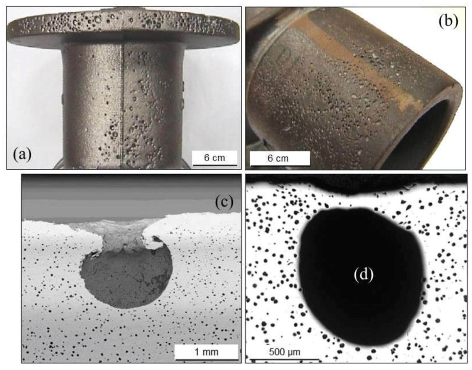
Defect 1: Gas Porosity
Gas porosity appears as spherical or elongated voids inside the casting or on its surface. These voids can be internal (detectable only by X-ray or sectioning) or external (visible as surface pinholes). Gas porosity compromises pressure tightness, reduces mechanical properties, and creates leak paths in critical components.
How Poor Gating Causes It
Poor gating design creates gas porosity through two primary mechanisms:
1. Air entrainment from turbulent filling: When metal enters the cavity turbulently, it folds over and entraps air. Research on magnesium alloy die casting confirms that “gas porosity correlates with turbulent flow patterns and the fluid’s inability to push gas bubbles away from the main casting” .
2. Aspiration: When the sprue is not tapered properly, the accelerating metal pulls away from the walls, creating a vacuum that sucks air and mold gases into the stream. P. Webster confirmed this phenomenon can actually be heard in a quiet foundry—the audible sound is air being aspirated into the metal .
How to Fix It
Solution 1: Design a tapered sprue
The sprue must be wider at the top and narrower at the bottom to maintain a full, liquid column throughout its length . This prevents the low-pressure conditions that cause aspiration.
Solution 2: Control gate velocity
Maintain gate velocity below the critical threshold of 0.5–1.0 m/s (lower for oxidation-sensitive alloys). Above this velocity, the metal surface becomes unstable, folding over and entraining gas .
Solution 3: Use filters and bubble traps
Ceramic filters break the flow into smaller streams and divert bubbles away from the cavity. Advanced designs like the trident gate incorporate bubble traps and multiple filters to eliminate gas entrainment .
Solution 4: Optimize runner geometry
Eliminate sharp corners in runners—they create low-pressure regions that draw in air. All corners must be smooth and rounded.

Defect 2: Slag and Dross Inclusions
Slag and dross inclusions appear as non-metallic particles embedded in the casting. In gray iron, these are typically furnace slag or eroded sand. In ductile iron, they are primarily magnesium silicates and sulfides formed by oxidation of the magnesium treatment . Inclusions act as stress concentrators, reduce fatigue life, and create machining difficulties.
How Poor Gating Causes It
Poor gating design creates inclusions through:
Inadequate slag trapping: Without proper traps, the first metal entering the system—which is often the coolest and dirtiest—flows directly into the cavity .
Excessive turbulence: In ductile iron, turbulence exposes fresh metal surfaces to air, causing magnesium to oxidize and form dross inclusions . Unlike gray iron, which is “not a dross-forming alloy,” ductile iron is highly reactive and generates inclusions during turbulent flow .
How to Fix It
Solution 1: Include runner extensions
Add a runner extension beyond the last gate—a “slag trap” that catches the first, dirtiest metal entering the system .
Solution 2: Use ceramic filters
Filters placed in the runner or sprue well trap inclusions before they enter the cavity. For ductile iron, floating ceramic foam filters at the bottom of risers have proven particularly effective .
Solution 3: Design for tranquil filling
Use unpressurized systems and bottom gating for ductile iron to minimize the turbulence that creates dross . Maintain gate velocities strictly below 0.5 m/s.
Solution 4: Position gates away from runner ends
Research shows that gates placed too near the end of the runner receive the dirtiest metal . Maintain adequate distance from the runner end to the first gate .
Defect 3: Cold Shuts and Misruns
Cold shuts appear as lines or seams on the casting surface where two metal streams met but failed to fuse completely. Misruns occur when the mold cavity does not fill completely, leaving unfilled regions. Both defects indicate inadequate fluidity and premature solidification.
How Poor Gating Causes It
Poor gating design causes cold shuts and misruns through:
Insufficient filling speed: If the gating system restricts flow excessively, the metal may freeze before the cavity is full .
Poor gate placement: Gates positioned such that metal must travel long distances through thin sections can cause the leading edge to cool before reaching the end of the cavity.
Inadequate temperature distribution: Bottom gating creates an unfavorable temperature gradient—the hottest metal enters at the bottom, leaving cooler metal at the top that may not flow completely .
How to Fix It
Solution 1: Increase gate size
Larger gates reduce flow velocity but increase flow rate. Calculate the optimal balance between velocity control and filling time.
Solution 2: Reposition gates
Place gates to minimize flow distances and direct metal toward the largest thermal masses first .
Solution 3: Consider top gating
For shallow castings, top gating places the hottest metal at the top, promoting better filling of thin sections . However, balance this against increased turbulence risk.
Solution 4: Use multiple gates
For large or complex castings, multiple gates ensure even distribution and reduce the distance metal must travel from any single entry point .
Defect 4: Shrinkage Porosity
Shrinkage porosity appears as irregular, branched voids (often with dendritic morphology) in regions that solidified last without access to liquid metal. Unlike gas porosity, shrinkage voids are not spherical and typically occur in thicker sections or thermal centers.

How Poor Gating Causes It
Poor gating design creates shrinkage porosity through:
Ingate root overheating: When metal flows through a constricted gate into a larger cavity, turbulence and friction generate additional heat at the gate-casting junction. This creates a persistent hot spot that remains molten after surrounding areas have solidified, leading to isolated shrinkage .
Feeding path blockage: Gates positioned such that thin sections lie between the gate and thick sections can cause early solidification of the thin sections, blocking the feeding path to the thick region .
How to Fix It
Solution 1: Increase gate-casting distance
When overheating at the ingate root causes shrinkage, moving the gate away from the casting shifts the hot spot into a less critical area . The investment casting case study on large plain parts solved shrinkage by adding a pad on the casting side, increasing distance .
Solution 2: Add chills at the ingate
For AlSi7Mg turbocharger castings, adding a copper plate at the ingate completely eliminated macro-porosity by accelerating solidification at the gate .
Solution 3: Position gates to feed thick sections directly
Ensure a clear feeding path exists from the gate directly to thick sections requiring feeding . Avoid placing gates only into thin sections adjacent to thick ones.
Solution 4: Use multiple ingates
For complex castings, multiple ingates positioned to feed different thick sections ensure liquid metal reaches all regions requiring feeding . Design one gate with a larger feeding modulus to remain liquid longest .

Defect 5: Sand Inclusions and Erosion Defects
Sand inclusions appear as embedded grains of mold material in the casting. Erosion defects show as rough, washed-out areas on the casting surface where mold material has been removed by flowing metal. Both indicate mold wall failure during filling.
How Poor Gating Causes It
Poor gating design causes sand inclusions through:
Excessive velocity: High-velocity metal streams erode sand from mold walls, washing inclusions into the casting. A gray iron flywheel case study found that high velocities in the sprue and sprue well were causing mold erosion, with eroded sand particles washing into the cavity.
Poor gate positioning: Gates directing metal to impinge directly on mold walls or cores cause localized erosion.
How to Fix It
Solution 1: Reduce gate velocity
The gray iron flywheel case study achieved an 80% reduction in scrap rate by reducing average gate velocity from 0.57 m/s to 0.49 m/s (and peak velocities from 1.47 m/s to 0.64 m/s) .
Solution 2: Redesign sprue well
A properly designed sprue well dissipates kinetic energy before metal enters the runner, preventing the high-velocity jets that erode runner walls .
Solution 3: Position gates to avoid direct impingement
Direct metal to strike mold walls at glancing angles rather than perpendicularly. Use multiple gates to distribute flow energy.
Solution 4: Use filters
Filters reduce velocity and break the stream into smaller, less erosive flows .
Defect 6: Hot Tears and Cracks
Hot tears are cracks that form during solidification when tensile stresses develop in regions where the metal is still weak. They appear as irregular, branching cracks, often intergranular, and may be oxidized if they form at high temperature.
How Poor Gating Causes It
Poor gating design contributes to hot tears through:
Unfavorable temperature gradients: Gating that creates steep temperature gradients can generate high thermal stresses as regions solidify at different rates.
Restrained contraction: Gates that create rigid connections between the casting and the gating system can restrain natural contraction during cooling, inducing tensile stresses.
How to Fix It
Solution 1: Design gates to shear easily
Gates should be narrow enough to break easily during cooling, allowing the casting to contract freely without restraint from the gating system.
Solution 2: Promote uniform temperature distribution
Use gating designs that distribute heat evenly throughout the cavity, minimizing steep gradients .
Solution 3: Consider gate location relative to casting geometry
Place gates near regions that can accommodate stress without cracking, avoiding thin sections that may tear.
Solution 4: Use simulation to identify stress concentrations
Modern casting simulation can predict regions at risk for hot tearing based on temperature and stress distributions .
Defect 7: Carburization and Surface Hardening (For Specific Alloys)
In certain alloys, particularly stainless steels and nickel-based alloys, carbon pickup from mold materials or gating components can cause localized carburization, leading to hard spots, reduced corrosion resistance, and cracking.
How Poor Gating Causes It
Poor gating design causes carburization through:
Improper gating material selection: Using carbon-bearing materials in contact with molten alloys that readily dissolve carbon.
Excessive turbulence: Turbulent flow increases contact between the metal and carbon-containing mold materials, accelerating carbon pickup.
How to Fix It
Solution 1: Use ceramic or refractory gating components
For alloys sensitive to carbon pickup, use ceramic gating components instead of traditional sand or carbon-bearing materials.
Solution 2: Minimize surface-to-volume ratio
Design gating with large cross-sections to minimize the surface area of metal exposed to carbon-bearing materials relative to volume.
Solution 3: Reduce turbulence
Tranquil filling reduces the washing action that accelerates carbon dissolution from mold surfaces .
Summary: Defects, Causes, and Solutions
| Defect | Primary Gating Causes | Key Solutions |
|---|---|---|
| Gas Porosity | Turbulent filling, aspiration, high gate velocity | Tapered sprue, velocity control, filters, bubble traps, rounded runner corners |
| Slag/Dross Inclusions | Inadequate slag trapping, turbulence in reactive alloys | Runner extensions, filters, tranquil filling (bottom gating, low velocity), proper gate positioning |
| Cold Shuts/Misruns | Insufficient flow rate, poor gate placement, unfavorable temperature gradient | Larger gates, multiple gates, strategic positioning, top gating for shallow parts |
| Shrinkage Porosity | Ingate root overheating, blocked feeding paths | Increase gate-casting distance, add chills, direct feeding paths, multiple gates |
| Sand Inclusions | Excessive velocity, mold erosion, direct impingement | Reduce gate velocity, proper sprue well design, avoid direct impingement, filters |
| Hot Tears | Restrained contraction, steep temperature gradients | Easily-shearing gates, uniform temperature distribution, strategic gate placement |
| Carburization | Carbon pickup from mold, excessive turbulence | Ceramic components, minimize surface-to-volume ratio, reduce turbulence |
The Cost of Poor Gating Design
The financial impact of gating-related defects is substantial. Documented case studies illustrate the potential savings from optimized design:
-
Gray iron flywheel: Over 4% internal scrap and customer rejects exceeding 26% in some months. Gating redesign reduced rejections, saving over $100,000 annually, with a 7% yield improvement adding another $150,000 .
-
Ductile iron housing: 22% scrap for dross-related defects, costing $118,000 annually. Gating modification dropped scrap to 3.6%, saving $118,000 annually plus $4,000 from yield improvement .
-
Gray iron hot plates: Optimizing gating ratio from 1:1.1:1.9 to 1:1.4:2.4 achieved significant quality improvements .
Prevention: The Role of Simulation
Modern casting simulation tools (MAGMAsoft, FLOW-3D, ProCAST) enable engineers to identify and correct gating-related defects before cutting tooling. Simulation can predict:
-
Flow patterns and air entrainment
-
Temperature distribution and solidification sequences
-
Shrinkage porosity locations
-
Oxide film generation and bubble entrainment
-
Stress distributions and hot tear risk
The magnesium alloy aircraft pod case study demonstrated how ProCAST simulation enabled optimization of ingate locations to eliminate shrinkage defects . The ADC12 crossbeam study showed how MAGMASOFT optimization achieved first-shot production success with high-integrity castings .
Conclusion
Poor gating system design is the root cause of seven common casting defects: gas porosity, slag inclusions, cold shuts, shrinkage porosity, sand inclusions, hot tears, and carburization. Each defect has specific gating-related mechanisms and corresponding solutions.
The common thread across all solutions is controlled, tranquil filling. By maintaining velocities below critical thresholds, designing for smooth flow transitions, incorporating filters and traps, and positioning gates strategically, foundries can eliminate the majority of gating-related defects.
The documented case studies prove that investing in proper gating design—and validating designs with simulation—pays substantial dividends through reduced scrap, improved quality, and significant cost savings.